


This was going to be the first blog of my line follower project made with Op-Amps. Unfortunately I have ruined the Op-Amps due to an error when going to test them. My lessons learned.
Project Blogs
MCP6007 Op Amp and more from Maxim Integrated / Analog Devices
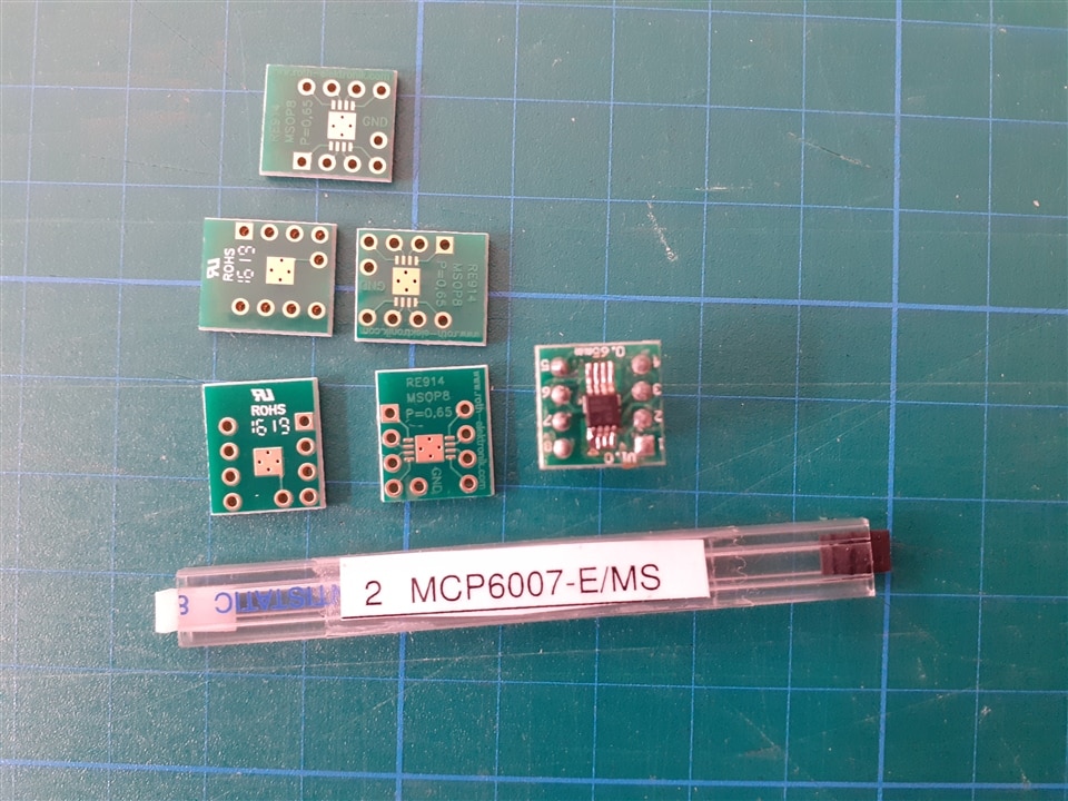
I received some 8-lead SOIC MSOP packaged Microchip MCP6007 Op-amps.
MCP6007-E/MS 2 OpAmps , 1 MHz, 1.9 V/µs, 1.8V to 5.5V, MSOP, 8 Pin
Supply Voltage Range: 1.8V to 5.5V
Vdd - Vss = 6 V max. (This was my mistake, I got distracted, I didn't respect the limits and I broke the Op-Amps when testing all of them  )
)
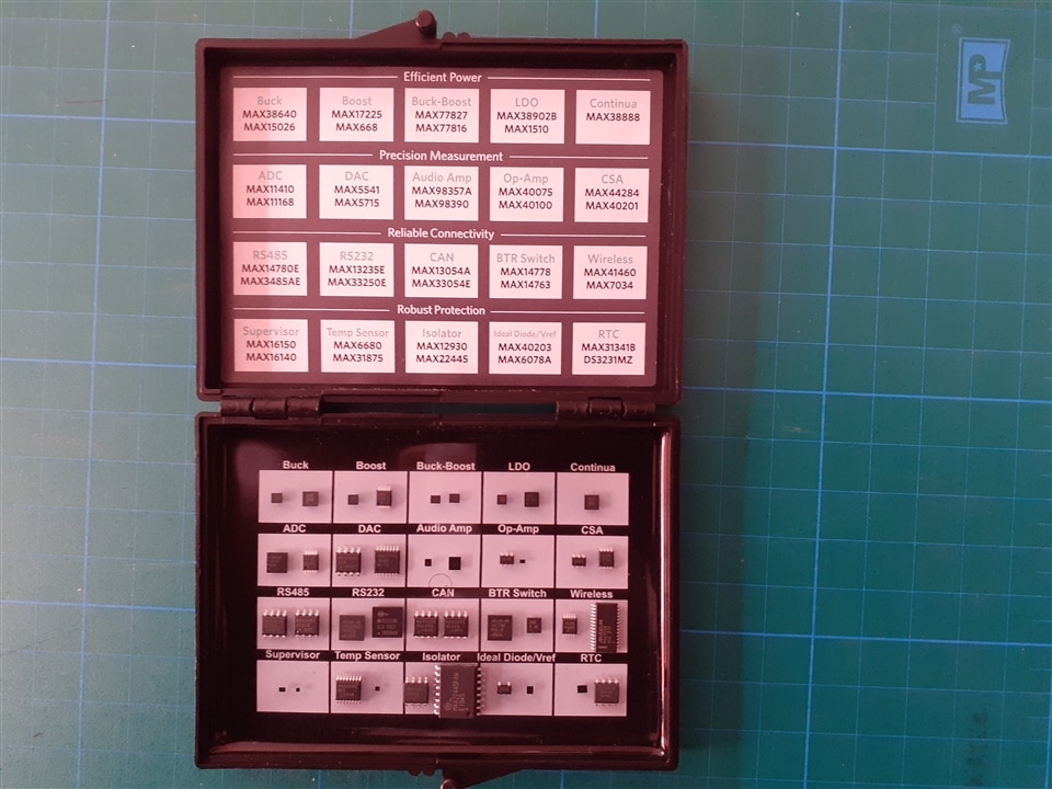
Along with the op-amps I also received this Essential Analog Toolkit from Maxim Integrated / Analog Devices. Kit from which I hope to be able to use more than one component in future projects.
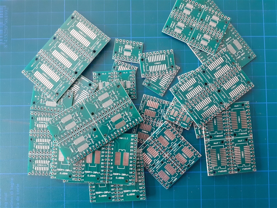
MSOP to DIP adapters
I don't have much experience with Op Amps. My idea was to first experiment with them and then build a working circuit.
I wanted to use a breadboard for testing and then a Eurocard prototyping board.
So I bought some MSOP to DIP adapters from Amazon.
The adapters are very curious, they are two-sided and each side is for a different footprint.
I also ordered these others in the shopping basket of the prize of another edition of Project14, but they arrived late.
Roth Adapter MSOP8
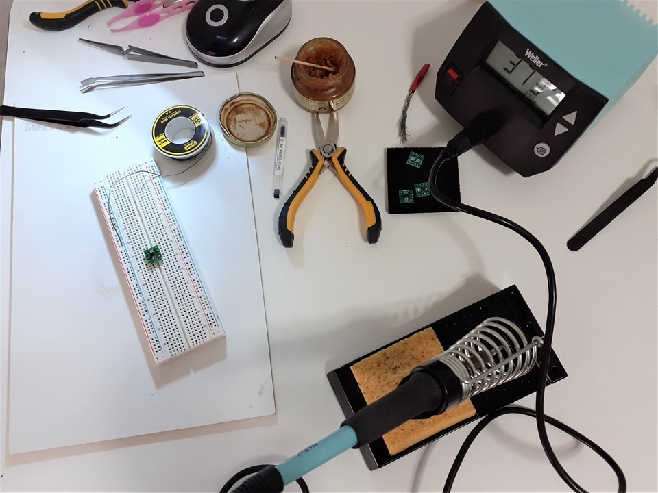
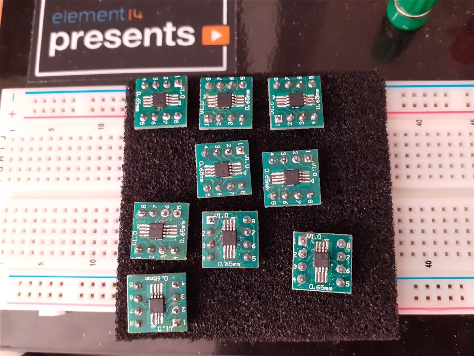
I soldered the op-amps to the adapters. I soldered them on a breadboard, first soldering the side pin headers to have a good hold on the base.
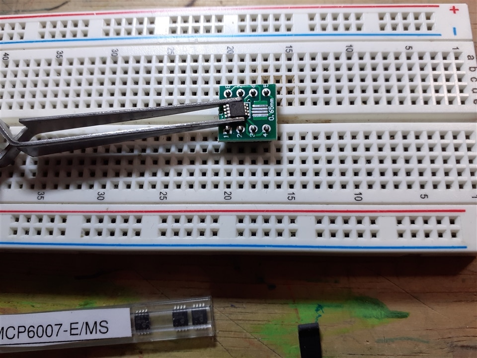
I used a Weller WE 1010 soldering station with a 0.8mm conical tip.
The first one cost me a lot to solder it, I soldered too much and it was difficult to eliminate all the short circuits.
The following with the lesson learned, a lot of flux and little tin was an easier task than I had thought.
Testing the Line Follower Stages
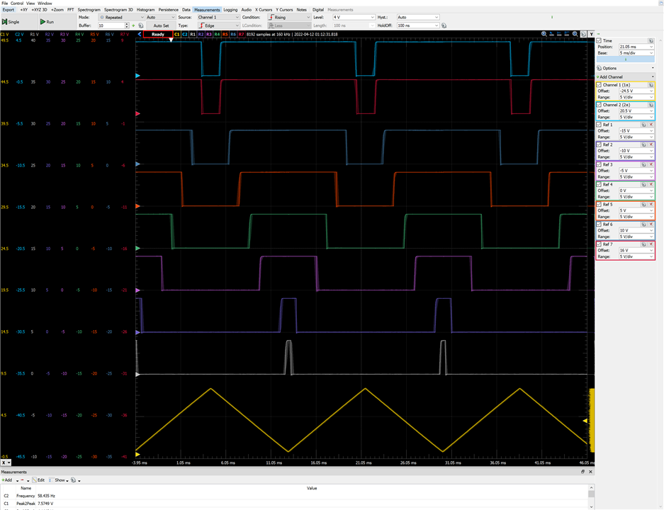
The next task in my plan was to test the different stages of the line follower separately: Triangular Wave Generator for PWM Controller, PWM Controller, Motor Drivers, Voltage Regulator and Virtual Ground, Line Sensor Adder, PID Control, Wheels speed adjustment.
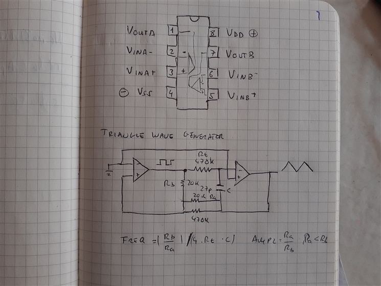
Triangle wave oscillator
The PWM controller was made of a triangular wave oscillator and a comparator. The triangle wave oscillator creates a symmetrical triangle wave.
The triangle wave oscillator first uses an integrator with a constant dc input voltage to generate a ramp. The integrator output drives a Schmitt trigger. The output of the Schmitt is what ought to determine the direction of the ramp. And use its output as the input to the integrator.
The Schmidt Trigger uses positive feedback to prevent multiple output transitions. (Ref: The Art Of Electronics. Horowitz/Hill)
I built the circuit on a breadboard.
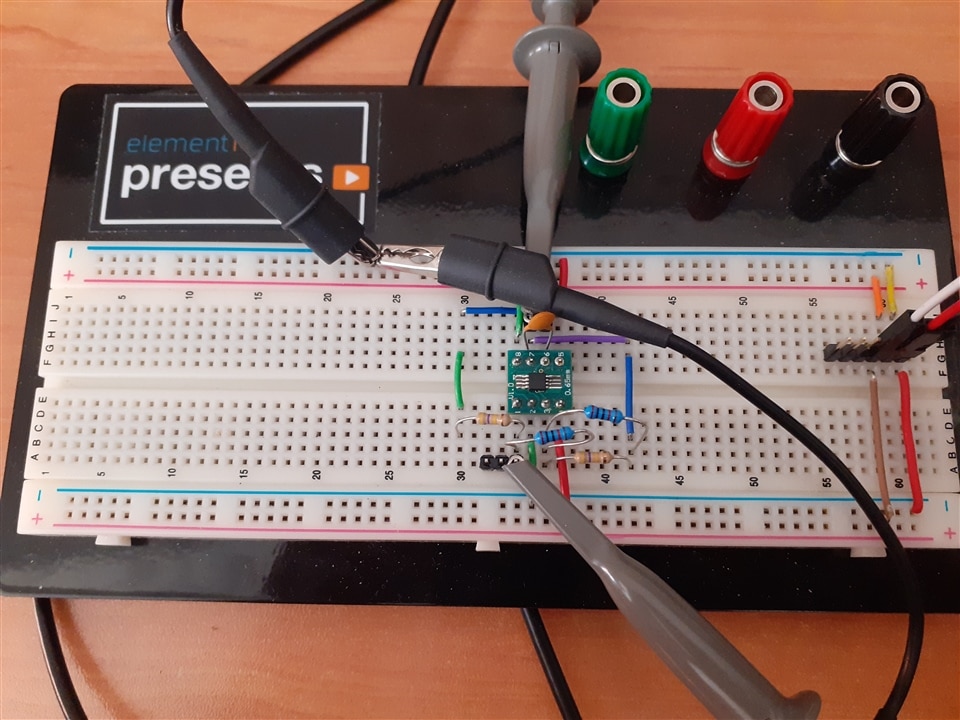
The values are known from a circuit that I searched for on the Internet, later if it works I will adjust to what interests me. At the moment I want to see something that works.
Theoretical calculation of the frequency:
- Rt = 470 kΩ
- Rb = 20 kΩ
- Ra = 20 kΩ || 470 kΩ = 19 kΩ
- C= 45p
- Freq = (20/19) / (4 *45e-12 * 470e3) = 12442.45365186
I was expecting a 12 kHz frequency but it only reaches 9.7 kHz

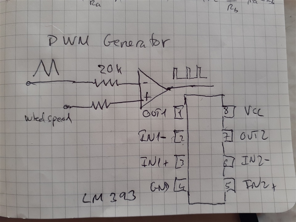
PWM Generator
The next stage is going to generate a PWM (Pulse Width Modulation) signal using a comparator and the triangular wave generated by the oscillator from the previous stage.
The circuit needs two PWM generators, one for the motor on the right and one for the motor on the left.
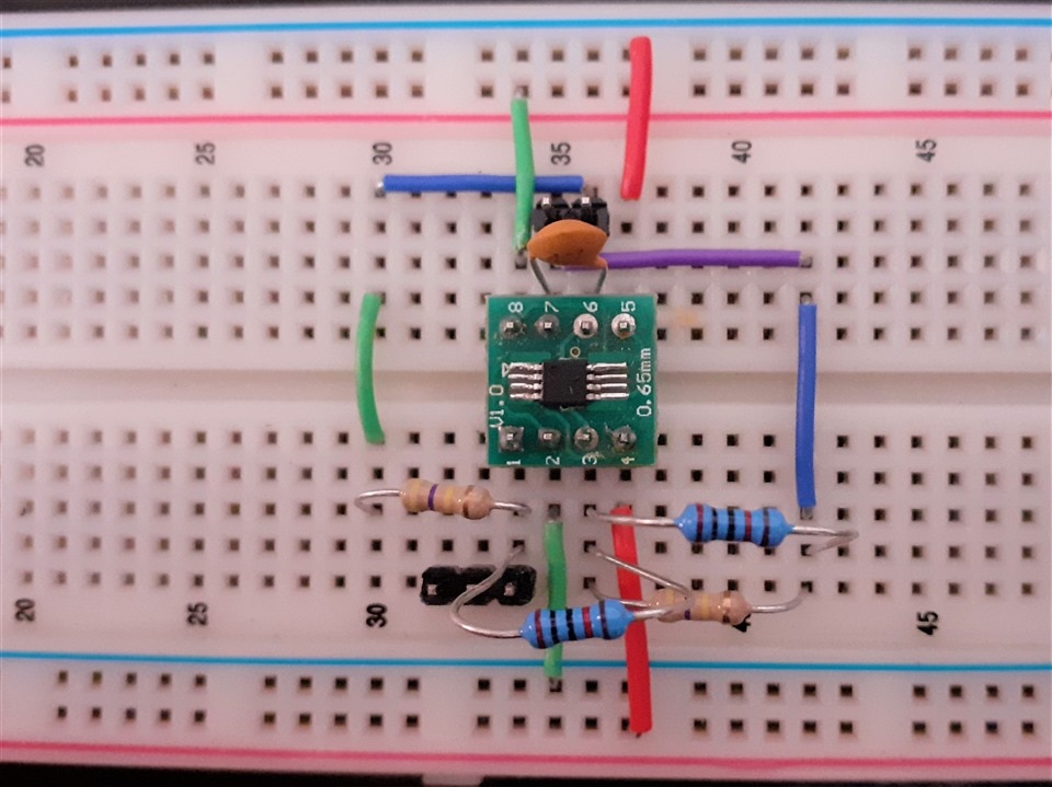
For the comparator I used an LM393P Dual Voltage Comparator
I haven't adjusted the frequency to the values I'm interested in yet. At these frequencies the chosen comparator did not give good results,
According to this article https://learn.adafruit.com/improve-brushed-dc-motor-performance/choosing-decay-mode-and-pwm-frequency the motor winding works best when the applied voltage is relatively stable, as it takes time for its magnetic field to build up to the necessary strength. At higher PWM frequencies, the motor driver board pulses change too quickly to provide enough power to spin the motor.
Slow decay mode is typically selected for controlling brushed DC motors due to its ability to dynamically apply braking. It also helps linearize the relationship between duty cycle and motor speed.
Most small brushed DC motors will work fine with a PWM frequency of 50Hz to 100Hz and a slow decay mode.
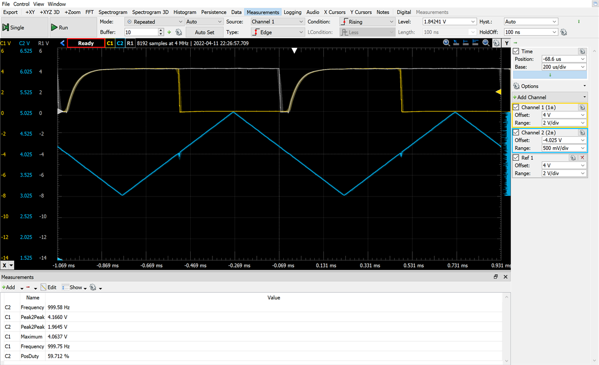
I tried with a frequency of about 56 Hz changing the capacitor to 10 nF. At this frequency the LM393 works better.
Theoretical calculation of the frequency:
- Rt = 470 kΩ
- Rb = 20 kΩ
- Ra = 20 kΩ || 470 kΩ = 19 kΩ
- C= 10 nF
- Freq = (20/19) / (4 *10e-9 * 470e3) = 55.9910414334 Hz
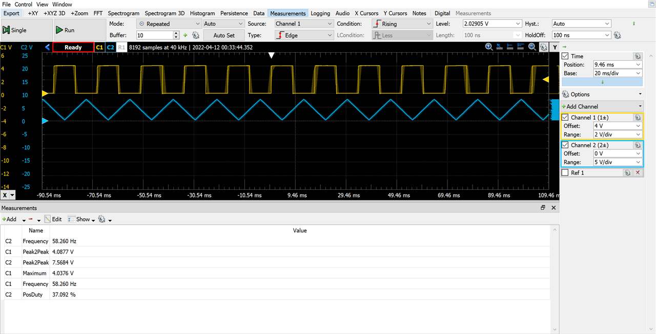
The stimulus variation changes the duration of the pulse from 0% to 100% positive duty cycle.
The circuit with a single comparator, later add the second comparator for the other wheel.

Controlling two PWM Outputs for the left and right motors
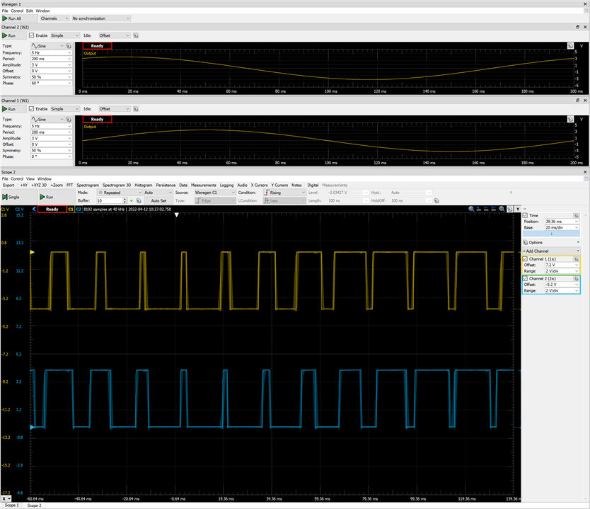
Circuit with the two comparators. The two function generators of the Analog Discovery 2 are generating two phase-shifted sinusoidal signals to see the behavior of the PWM generator.

Stimulus simulation for left and right motors
At this point, instead of going for a walk I decided to test if all the Op-Amps I had received worked and compare their response.
But something didn't work.
I didn't check well and I don't know for what stupid reason I tried them all and broke them all. They are now shorted from Vdd to Vss.
Next steps
- First I'll go for a walk.
- Next I'll try to continue the project with other Op-Amps but this time slowly.
Top Comments