element14 Community
element14 Community
    Register Log In
  • Site
  • Search
  • Log In Register
  • About Us
  • Community Hub
    Community Hub
    • What's New on element14
    • Feedback and Support
    • Benefits of Membership
    • Personal Blogs
    • Members Area
    • Achievement Levels
  • Learn
    Learn
    • Ask an Expert
    • eBooks
    • element14 presents
    • Learning Center
    • Tech Spotlight
    • STEM Academy
    • Webinars, Training and Events
    • Learning Groups
  • Technologies
    Technologies
    • 3D Printing
    • FPGA
    • Industrial Automation
    • Internet of Things
    • Power & Energy
    • Sensors
    • Technology Groups
  • Challenges & Projects
    Challenges & Projects
    • Design Challenges
    • element14 presents Projects
    • Project14
    • Arduino Projects
    • Raspberry Pi Projects
    • Project Groups
  • Products
    Products
    • Arduino
    • Avnet Boards Community
    • Dev Tools
    • Manufacturers
    • Multicomp Pro
    • Product Groups
    • Raspberry Pi
    • RoadTests & Reviews
  • Store
    Store
    • Visit Your Store
    • Choose another store...
      • Europe
      •  Austria (German)
      •  Belgium (Dutch, French)
      •  Bulgaria (Bulgarian)
      •  Czech Republic (Czech)
      •  Denmark (Danish)
      •  Estonia (Estonian)
      •  Finland (Finnish)
      •  France (French)
      •  Germany (German)
      •  Hungary (Hungarian)
      •  Ireland
      •  Israel
      •  Italy (Italian)
      •  Latvia (Latvian)
      •  
      •  Lithuania (Lithuanian)
      •  Netherlands (Dutch)
      •  Norway (Norwegian)
      •  Poland (Polish)
      •  Portugal (Portuguese)
      •  Romania (Romanian)
      •  Russia (Russian)
      •  Slovakia (Slovak)
      •  Slovenia (Slovenian)
      •  Spain (Spanish)
      •  Sweden (Swedish)
      •  Switzerland(German, French)
      •  Turkey (Turkish)
      •  United Kingdom
      • Asia Pacific
      •  Australia
      •  China
      •  Hong Kong
      •  India
      •  Korea (Korean)
      •  Malaysia
      •  New Zealand
      •  Philippines
      •  Singapore
      •  Taiwan
      •  Thailand (Thai)
      • Americas
      •  Brazil (Portuguese)
      •  Canada
      •  Mexico (Spanish)
      •  United States
      Can't find the country/region you're looking for? Visit our export site or find a local distributor.
  • Translate
  • Profile
  • Settings
Photonics
  • Challenges & Projects
  • Project14
  • Photonics
  • More
  • Cancel
Photonics
Blog Easily LED
  • Blog
  • Forum
  • Documents
  • Events
  • Polls
  • Files
  • Members
  • Mentions
  • Sub-Groups
  • Tags
  • More
  • Cancel
  • New
Join Photonics to participate - click to join for free!
  • Share
  • More
  • Cancel
Group Actions
  • Group RSS
  • More
  • Cancel
Engagement
  • Author Author: paj
  • Date Created: 14 Apr 2020 7:07 PM Date Created
  • Views 3084 views
  • Likes 10 likes
  • Comments 25 comments
  • photonicsch
Related
Recommended

Easily LED

paj
paj
14 Apr 2020

  • Introduction
  • Experimenting
  • Research
  • More Experimenting
  • Finally a project

Introduction

When the photonics competition was announced I had no idea what I could do as an entry. Reading through the brief the only parts I have that I could usefully use in a project are LEDs. To date I have only used LEDs as indicators to signal that something is working so in a nutshell I know very little about them. To prove this I have jotted down what I know.

image

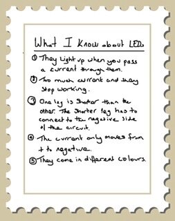
Even the things I know are a bit vague so I thought I would do some research and experimentation.

Experimenting

First thing I did was to put an led in a breadboard and take a photo.

image

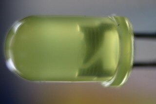
Then I powered the LED with 1v and nothing happened.

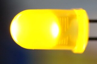
I increased voltage to 2v and the LED lit up.

image

Next  I increased the voltage and the LED failed in what looked like a small explosion. Video shows LED lit  normally then I turn off the power, increase the voltage and turn the power back on.

You don't have permission to edit metadata of this video.
Edit media
x
image
Upload Preview
image

So what is actually happening here?


Research

I started by Googling ‘Why does an LED explode?’ More than a few people seemed to take exception to this terminology but to be honest they didn’t clarify why they thought this was wrong. The posts were quite old so there is little point in trying to follow this line of thought. The best answer I could find was that the current caused the semiconductor material in the LED to overheat and eventually burn.

This makes some sense. Reading a bit more I found out that the LED is made up of a semiconductor. Semiconducting material has a forward voltage which is the point below which it will not allow the current to flow. This is why my LED did not light at 1V.  When you pass enough current through the semiconductor it allows the current to flow hence it lit at 2V. This happens by virtue of the electrons in the semiconductor becoming excited. In an ordinary diode this allows the current to flow in the LED it also creates photons and consequently light.  The non-conducting material in a semiconductor is doped with an another compound. Doping is a process of adding a minute quantity of another substance to the silicon base and it is this trace compound that creates the ability for the electrons to flow.  Different compounds create the different colours.

These are some of the different compounds used.

  • Indium gallium nitride (InGaN): blue, green and ultraviolet high-brightness LEDs,
  • Aluminum gallium indium phosphide (AlGaInP): yellow, orange and red high-brightness LEDs,
  • Aluminum gallium arsenide (AlGaAs): red and infrared LEDs,
  • Gallium phosphide (GaP): yellow and green LEDs.


I think what I have written, whilst brief, is correct (please point me in the right direction if I have missed the point somewhere). Anyway the physics beyond this point is getting more complicated than I want to get into (this branch of physics is on the rather large list of things that I don’t understand).
I noticed on the data sheet, that I looked at, there was a reverse voltage i.e. the voltage at which the diode will allow current to flow back. The data suggests that when this point is reached it is usually also the point at which the LED will fail.

More Experimenting

So back to experimenting and I put an LED in the bread board and reversed the voltage.

image

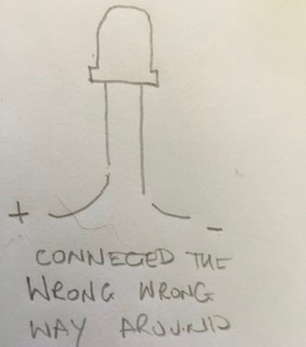
I started my camera recording and watched what happened as I cranked up the volts.

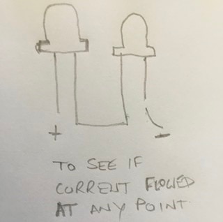
Nothing.  I started at 5V and reached 31V (the limit of my bench power supply) and what I expected, which was some sort of catastrophic failure, didn’t happen. I tested the LED and it still worked. So I connected another LED the right way around into the circuit to see if at any point the current flowed. Still nothing.

image

So from that I can conclude , for my LEDs at least, that they would act as a diode for quite a high current, certainly more than I ever play around with. I guess other LEDs will have different characteristics.

LED as a light sensor.


During my earlier research I read that an LED can be used for a light sensor because it creates a very small current in the presence of light. So I tested one with my multimeter.

In my little room, which is quite dark, my yellow LED registered 5.6mV. I tried a green LED and this registered 7.9mV. A red LED registered 6.9mV.  I tested another similar yellow LED and got 6.9mV , Another green 9.6mV another red 3.9mV. It was bright sunshine outside so the light levels weren’t fluctuating. So the results weren’t consistent. I have some super bright clear LEDs so I put one in 19.5mV. I tried another 18.7mV, another 21.9mV then another 21.2mV and back to the first 19.1mV. I then measured the values whilst  I held a 6V LED bulb above the LED.


Colour
First test mV Second test mV Third test mV Result of holding light above LED
Red 6.9 3.9 6.3 230mV
Yellow 5.6 6.9 7.1 140mv
Green 7.9 9.6 9.9 121mV
Clear (super bright) 19.5 18.7 21.9 33mV


The super bright LEDs are better quality so maybe that explains the more consistent voltage readings. Looking at my little table I think the voltage is differing according to the different colours. Also it is evident that each LED is responding to the light being shon eon it.

The other thing I read was that LEDs are colour sensitive so I did some experimenting with different colour LEDs and an RGB LED to provide the coloured light. I placed the coloured LEDs next to the RGB and then powered each leg on the RGB to get red green and blue light. Here are the results:

LED colour Room light mV Red light mV
Green light mV
Blue light mV
Red 1.2 5.1 1.2 1.2
Green 17.5 17.5 52.3 41.7
Yellow 8.3 8.1 33.9 10
Clear 39.4 40.3 40.1 41.4

From this I would say the red LED is definitely more sensitive to red light just as the green LED is more sensitive to the green light, but also quite sensitive to blue. I didn’t bother to try to power the RGB to make yellow but it responds quite strongly to the green light. The clear LED didn’t seem to respond.


Finally a project

Whilst I was experimenting I started thinking about what I could do as a project with LEDs and came up with the idea of a sun tracker. My plan was to embed 5 LEDs in tubes to form the shape of a plus sign. My idea being that as the light shone down the tube, in which the LED was embedded, the more directly the tube faced the sun the greater the voltage generated by the LED would be. I would use an analogue input pin on an Arduino UNO to measure the current generated by the LED. The plus sign of LEDs would be mounted on a pan and tilt assembly.

So I had already 3d printed a pan and tilt assembly some months ago (courtesy of Thingiverse)  that utilised a couple of cheap servos. So I got that out and wrote a script to make the pan and tilt scan through the various angles at which the sun could be situated.

You don't have permission to edit metadata of this video.
Edit media
x
image
Upload Preview
image

Next I generated a small script to capture values from the LED. The LED cathode is simply connected to the earth and the anode into the A0 socket. This seemed to work nicely, the values went up when the light was turned on and back down when the light was turned off.


You don't have permission to edit metadata of this video.
Edit media
x
image
Upload Preview
image


So now I needed to combine the two scripts but I knew both were too simplistic for a working sun tracker.

So I thought to get things started I would attach just one LED to the pan and tilt mechanism. I had a couple of male female jumper leads and I connected these to the LED and plugged them into the UNO. It was then I realised that it wasn’t going to work. The longer leads made the analogue pin sensitive to nearly anything and the values were leaping around by themselves. Sometimes dropping to 0 then rising and falling again. I think what is happening is that the A0 pin is responding to various sources of emf.

You don't have permission to edit metadata of this video.
Edit media
x
image
Upload Preview
image

So at this point I decided to call it a day and I didn’t actually intend to finish this blog. But then today I thought I would because it might interest someone and also someone might tell me something that I can do to fix this.

So any comments about anything that I might have gotten wrong (please be kind) or any ideas to solve this would be very welcome.
As I finally put this to bed I wonder if a capacitor would help?

  • Sign in to reply

Top Comments

  • jc2048
    jc2048 over 5 years ago in reply to paj +4
    Here's the circuit and a couple of pictures of it I didn't bother with a board, just floated it in mid-air above the UNO. This is the UNO code. It's extremely simple, just takes the pin high for 60us every…
  • paj
    paj over 5 years ago in reply to dubbie +3
    Hi Dubbie, can”t take the credit for the pan and tilt it was just something I found on thingiverse. My CAD skills aren’t quite up to that though I am getting there. I will take on board your thoughts oh…
  • jc2048
    jc2048 over 5 years ago +3
    I was curious about your reverse measurements. It's not something that you normally ever look at if you design with LEDs, you just go by what the datasheet tells you (which is usually 5V). I've tried it…
Parents
  • jc2048
    jc2048 over 5 years ago

    I was curious about your reverse measurements. It's not something that you normally ever look at if you design with LEDs, you just go by what the datasheet tells you (which is usually 5V).


    I've tried it with a few LEDs, but unfortunately I don't know what they are as they are from old bags that have been lying around for years (once upon a time, LEDs were part of my day job and these are some from spares that were kept on a storeroom shelf and never used). This is with a test current of about 20mA, but it's all a bit approximate. This isn't a piece of professional test equipment; it's just a lash-up with an Arduino, so take the results with a little skepticism.


    Here's a red, clear, high brighness, narrow viewing angle


    image


    Here's a green, fairly high brightness


    image


    Finally here's one I do know the part number of, it's a Kingbright L-7104ID red LED (GaAsP/GaP), which is impressive.


    image


    That last one is getting very 'iffy'. This is my test circuit without an LED


    image


    so it only reaches -180V anyway and at -170V it's running out of 'steam' [current really] and it's probably just increased leakage that's folding it over and not an actual, sustained avalache.


    All the above were happy to repetitively avalanch twice a second, but I also tried an old Nichia high-brightness true-blue and that failed almost immediately after showing a breakdown at about -70V. When they first came out they had to be treated carefully as static-prone components, so I'm not surprised it died quickly.


    The low datasheet figure might be down to what can be tolerated before it starts to compromise other things like the lifetime, rather than anything to do with where it breaks down and what damage might then ensue.


    As Fred27 points out, there's a relationship between the forward current and the forward voltage that you need to understand. If your power supply works constant-current to a reasonable accuracy, you could try increasing the current from about 1mA in small steps and seeing what the forward voltage is for each step. If you plot it on a graph, current against voltage, you'll soon see why applying 5V directly across the diode is problematic.

    • Cancel
    • Vote Up +3 Vote Down
    • Sign in to reply
    • More
    • Cancel
Comment
  • jc2048
    jc2048 over 5 years ago

    I was curious about your reverse measurements. It's not something that you normally ever look at if you design with LEDs, you just go by what the datasheet tells you (which is usually 5V).


    I've tried it with a few LEDs, but unfortunately I don't know what they are as they are from old bags that have been lying around for years (once upon a time, LEDs were part of my day job and these are some from spares that were kept on a storeroom shelf and never used). This is with a test current of about 20mA, but it's all a bit approximate. This isn't a piece of professional test equipment; it's just a lash-up with an Arduino, so take the results with a little skepticism.


    Here's a red, clear, high brighness, narrow viewing angle


    image


    Here's a green, fairly high brightness


    image


    Finally here's one I do know the part number of, it's a Kingbright L-7104ID red LED (GaAsP/GaP), which is impressive.


    image


    That last one is getting very 'iffy'. This is my test circuit without an LED


    image


    so it only reaches -180V anyway and at -170V it's running out of 'steam' [current really] and it's probably just increased leakage that's folding it over and not an actual, sustained avalache.


    All the above were happy to repetitively avalanch twice a second, but I also tried an old Nichia high-brightness true-blue and that failed almost immediately after showing a breakdown at about -70V. When they first came out they had to be treated carefully as static-prone components, so I'm not surprised it died quickly.


    The low datasheet figure might be down to what can be tolerated before it starts to compromise other things like the lifetime, rather than anything to do with where it breaks down and what damage might then ensue.


    As Fred27 points out, there's a relationship between the forward current and the forward voltage that you need to understand. If your power supply works constant-current to a reasonable accuracy, you could try increasing the current from about 1mA in small steps and seeing what the forward voltage is for each step. If you plot it on a graph, current against voltage, you'll soon see why applying 5V directly across the diode is problematic.

    • Cancel
    • Vote Up +3 Vote Down
    • Sign in to reply
    • More
    • Cancel
Children
  • Jan Cumps
    Jan Cumps over 5 years ago in reply to jc2048

    I should have submitted a happy bridge rectifier for Photonics  image.


    image

    • Cancel
    • Vote Up +2 Vote Down
    • Sign in to reply
    • More
    • Cancel
  • jc2048
    jc2048 over 5 years ago in reply to jc2048

    Here's another one.


    image


    That's a 1W warm white on a 'star' board. It seems to have a very low reverse breakdown voltage (the reading at the 'b'

    cursor point of -6.68V), compared to the ones above, but that's because we're most likely not looking at the breakdown of

    the LED itself. Instead it probably shows the voltage at which an internal anti-static diode is clamping.


    If you want to try this for yourself with some of your own LEDs (you'd need an oscilloscope, an Arduino UNO, and three

    simple components), say and I'll explain how I'm doing it and show you a picture.

    • Cancel
    • Vote Up +1 Vote Down
    • Sign in to reply
    • More
    • Cancel
  • jw0752
    jw0752 over 5 years ago in reply to jc2048

    Hi Jon,


    It may be on my end but your posts seem to be lacking a diagram or picture that is referenced in your text.


    John

    • Cancel
    • Vote Up +1 Vote Down
    • Sign in to reply
    • More
    • Cancel
  • Jan Cumps
    Jan Cumps over 5 years ago in reply to jw0752

    neuromodulator 's calibration post has the issue too. The forum seems to have an issue.

    • Cancel
    • Vote Up +1 Vote Down
    • Sign in to reply
    • More
    • Cancel
  • jw0752
    jw0752 over 5 years ago in reply to Jan Cumps

    It is the weekend isn't it.

    • Cancel
    • Vote Up +1 Vote Down
    • Sign in to reply
    • More
    • Cancel
element14 Community

element14 is the first online community specifically for engineers. Connect with your peers and get expert answers to your questions.

  • Members
  • Learn
  • Technologies
  • Challenges & Projects
  • Products
  • Store
  • About Us
  • Feedback & Support
  • FAQs
  • Terms of Use
  • Privacy Policy
  • Legal and Copyright Notices
  • Sitemap
  • Cookies

An Avnet Company © 2025 Premier Farnell Limited. All Rights Reserved.

Premier Farnell Ltd, registered in England and Wales (no 00876412), registered office: Farnell House, Forge Lane, Leeds LS12 2NE.

ICP 备案号 10220084.

Follow element14

  • X
  • Facebook
  • linkedin
  • YouTube