


Introduction
I recently had the pleasure of Building Frank's Milliohm Meter a project by fmilburn that was a Project14 Test Instrumentation entry. I thought it would be nice to use his Project14 project, to build my Project14 project : )
Enter the miniature speaker simulator : ) It is a really easy-to-assemble project. Here is an 8-minute overview and demo video:
It is basically a dummy load, that can take the place of a real speaker when testing hi-fi or car stereo amplifiers. It saves having to blast out loud music each time you want to test. I briefly considered the “buy a cheap speaker and punch out the cone” school of thought, but that wouldn’t make a particularly interesting project : )
Another approach could be to buy a load of power resistors and just use them (this was the nicest-looking dummy load project I found). However, they require attaching to a large heatsink or enclosure usually (for example a 30x30cm sheet of aluminium for dissipating 25W). So, that was an option, but sometimes it is fun trying something different – not necessarily better, just different.
So, I looked around and decided to build something a bit like a hairdryer – consisting of a coil of wire that gets hot, and a fan to blast the heat out. There are many advantages, and some disadvantages to this approach.
I liked that it could potentially be a lot smaller than the power resistors and aluminium heatsink method. The heat-generating end of a hairdryer isn’t very large usually. Also, I liked the idea of providing multiple arbitrary taps off the coil, so that it could almost act like a rheostat – the user could select where to tap off the connection, in order to simulate 2 ohm, 4 ohm or 8 ohm speakers. Another benefit is the accuracy; the home-made load could be quite precise, because Frank’s project is precise. Many low-cost power resistors have 5% tolerance, but I was aiming for 1% tolerance or better, for no reason other than it is possible.
The main disadvantages to the chosen solution are that a power source is needed to run the fan, and of course there will be some noise from the fan too. Still, I decided to go with it and attempt this design, to see if it worked out.
The end result was a very compact design (160x60x60mm) that can easily handle 200W of continuous power, and may go further (I briefly tested at 300W too). The fan noise concern was found not to be an issue; the chosen 12V fan12V fan was very quiet – perhaps too quiet, it is easy to forget if the fan is switched on (I inadvertently used the load at 200W with the fan switched off for a few seconds, and it survived!).
Building It
The core of the design is a coiled coil of resistance wire. It is supported by being threaded through a circuit board structure while it is wound into a coil. It’s not very difficult because only half a dozen turns are required before it is threaded into the next hole. Each complete pass around the PCB structure is terminated using a crimped ferrule (see Knipex Self Adjusting Crimping Plier - Review for details on this).
The PCB structure is made of a couple of identical boards, that have a half length slit down the center, allowing an X-shape to be created (it is secured with solder along the center.
The resistance wire was cut up into 8 pieces because the aim is to have a total of 8 passes around the PCB structure.

This type of design results in some inductance, but I didn’t mind that – it would be a good test for the connected amplifier, since it needs to be able to handle even higher inductance from a real speaker.
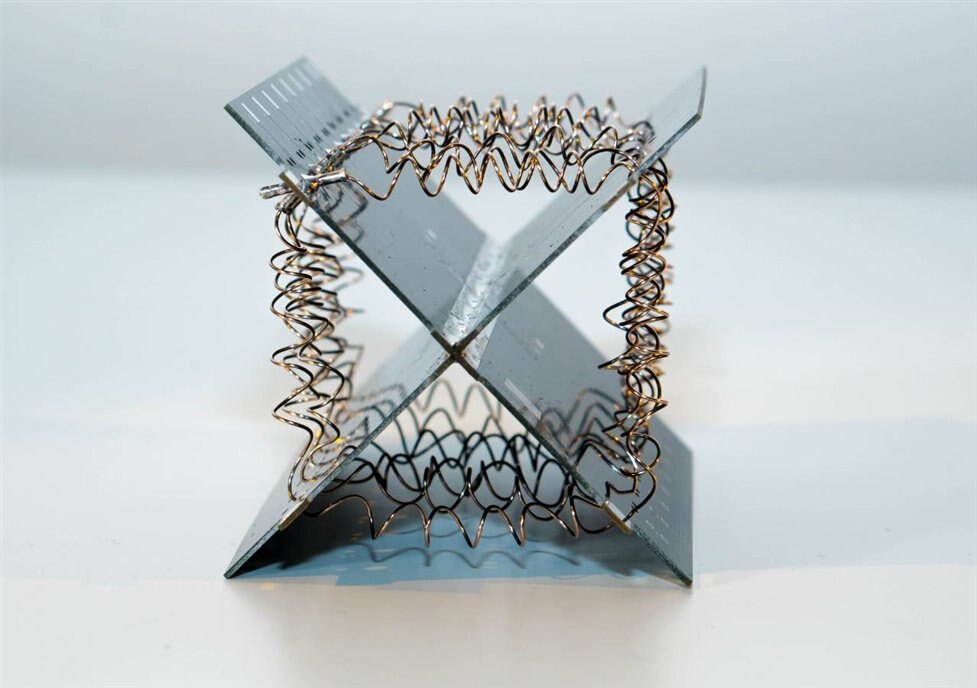
Here’s a closeup of the crimped complete passes around the structure; there are a total of 8 passes, each of 1 ohm resistance, for 8 ohm overall sum. Each pass has to go through the four quadrants of the structure. The milliohm meter can be used to decide how long the wire should be, or it can be calculated if the wire resistivity and wire diameter is known. I found I only needed about 6 turns around a 4mm shaft, to equal 0.25 ohms. If 0.45mm diameter Manganin is used (order code MN0450-050 from wires.co.uk), then a length of 37.0cm of it will equal 1 ohm.

The end result looks like this:
I wanted to bring each of the 8 passes out to a wire connection, so that they could be attached to 4mm banana sockets or binding posts. I’ve not got a better method for this yet (perhaps some 45 degree connectors exist), but the procedure here works, and was surprisingly easier than I initially expected.
It relies on a PCB that is soldered on one side of the structure, and thin copper sheet cut into tabs that are used as interconnect.
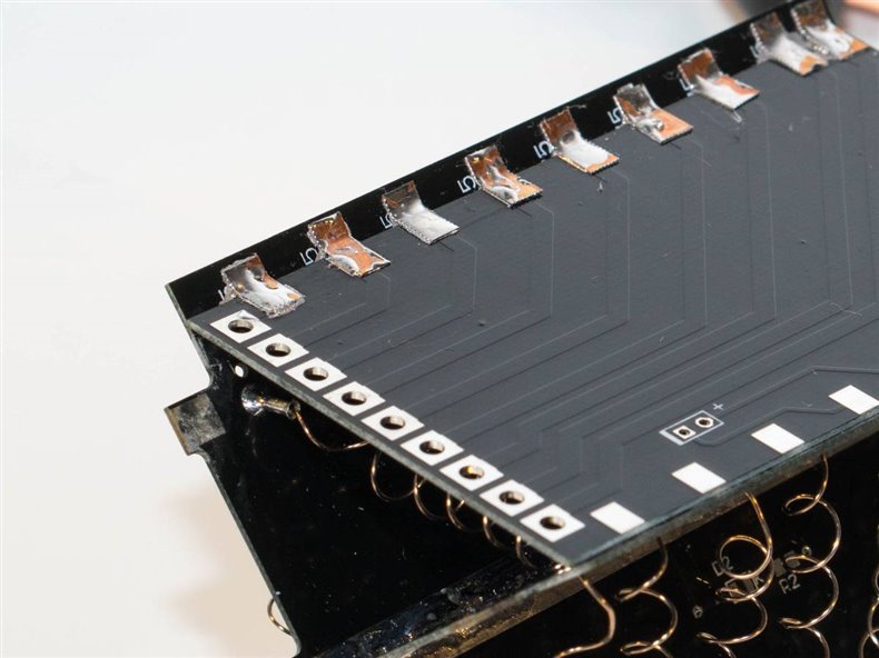
To do this, cut the thin copper sheet into small pieces, and then approximately bend at 45 degrees using pliers:

Next, apply some solder paste to the pads on the PCB, and hold the copper tabs in place with tweezers. A large soldering iron will melt the paste and attach the tab to both PCBs simultaneously. The tweezers are used to keep the tab in place until it cools. I attached wires onto the winding taps that I wanted (I just went with 4 ohm and 8 ohm for now).
Some Kapton tape was used for insulation over the copper tabs, just in case something unexpected happens during operation.

The diagram below shows how this PCB structure will fit inside the aluminium chassis.

Some of the bits and pieces are shown in the photo below. To hold the fan in position, triangular aluminium corner brackets were made, and tapped with M3 thread (to do that, drill a 2.5mm hole, and then use M3x0.5mm tapsM3x0.5mm taps with a hand tap wrenchhand tap wrench). Epoxy glue was used to secure them in place.

The photo below shows the fan end of the system. The PCB structure was slid into the box section tube, and then the connections were made to the binding posts. If desired, thin insulating sheets could be used against the inner walls of the tube - spare microwave waveguide cover sheets are available from amazon.

A small DC power connectorDC power connector and LED were fitted on the opposite side to the binding posts, so that the top and bottom surfaces were flat, for stacking multiple units.
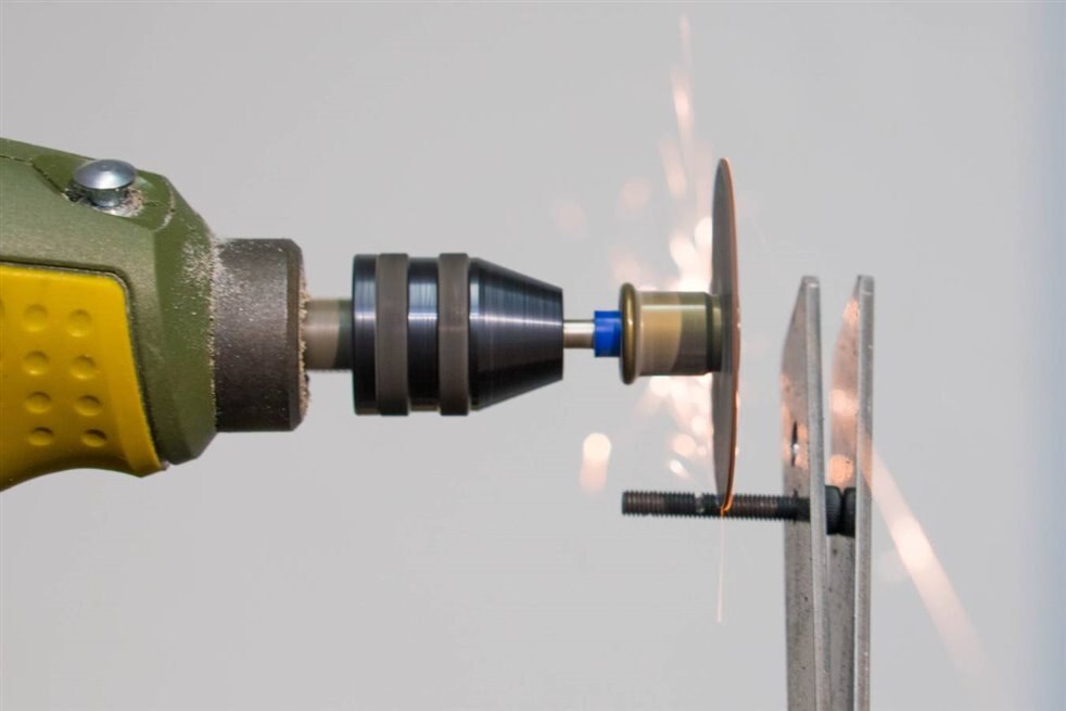
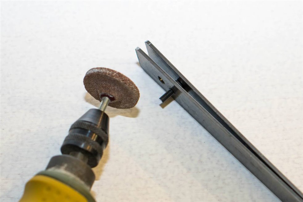
Incidentally, for securing the fan, I needed to cut some M3 screws because I didn’t have the correct ones. There was an excellent screw shortening method in an online video. In a nutshell, a couple of pieces of steel are cut and bolted or riveted at one end. Holes for screws are made at the other end of one of the pieces.
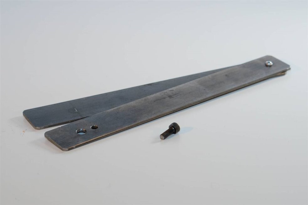
Then, place the screw in there, and use a Dremel or Proxxon high-speed tool with a cutting wheel! (wear glasses).
Afterwards, use a grinding wheel to put a small bevel around on the cut edge.
The other end of the dummy load needed a fan coverfan cover too, but I didn’t wish to permanently glue it, nor did I want to drill holes on the sides of the enclosure. The solution was a friction-fit design using four aluminium posts.

Labelling It
I’ve not labelled it yet, but I think I’ve got a great idea for future projects – enamelling! My crude first attempt is shown below.
It was trivially easy – cut a shape (or use a stencil) for your desired design or lettering. Sprinkle the enamel on top, and then carefully lift off the shape/stencil without sneezing. The enamel needs to be heated, ideally from the underside. This was done using small candles placed inside the tube. After about five minutes (there is a lot of metal to heat up) the enamel will melt and adhere to the tube! The metal will get extremely hot (enough to burn your hand), it will take a long time for it to cool down too. The end result seems pretty tough.

Testing It
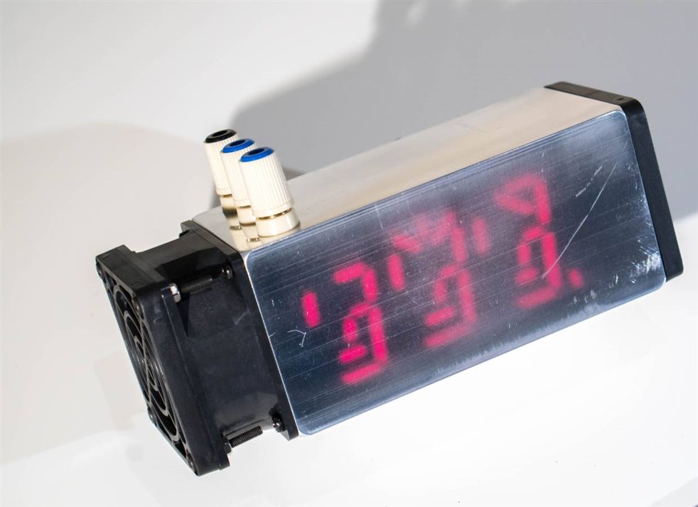
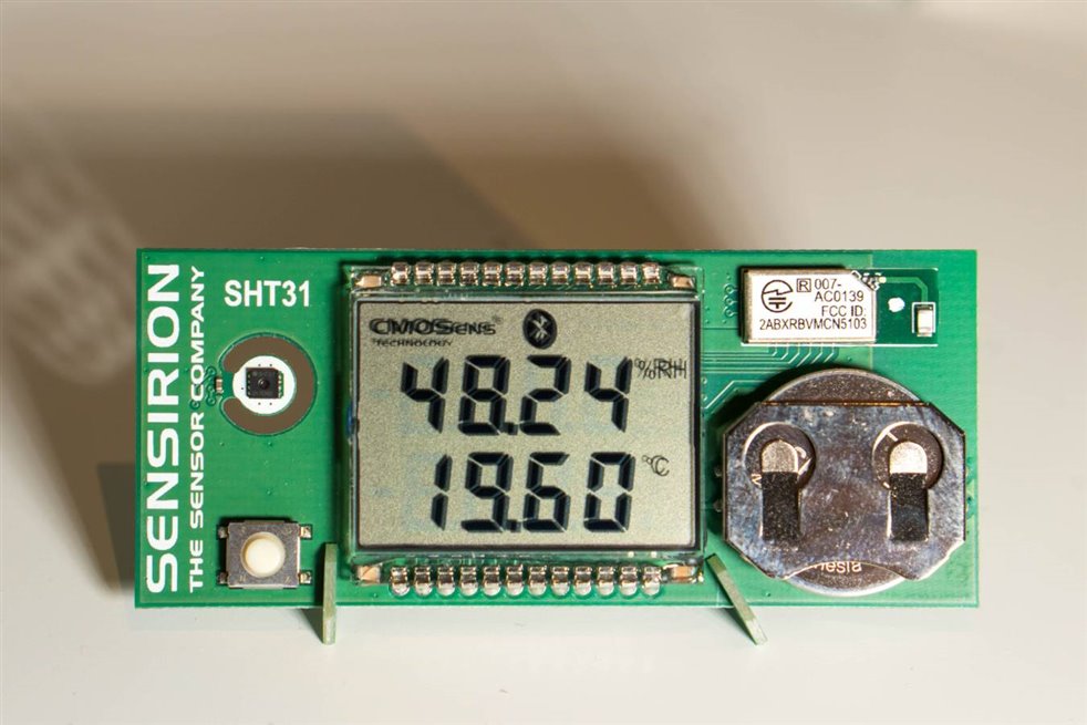
After some basic tests to confirm there were no shorts, I connected it up to a power supply and tried getting it to dissipate 100W. It did that fine, so I upped it to 200W, the maximum for my power supply. No problem! Lots of heat was blown out (the temperature of the hot air was observed using this unusual Sensirion logging thermometerSensirion logging thermometer) and the aluminium enclosure remains cool. The resistance did not change. The wire does permanently change color due to oxidisation, and this could be prevented if it had a protective heat-resistant coat. However, we're not making a precision reference resistor, so I felt this was unnecessary, since the aim was just 1% tolerance.
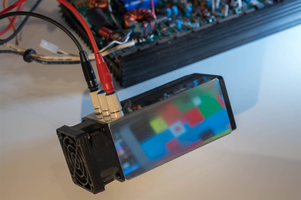
For higher power testing, I used a massive door-stop 48V 10A power supply. It weights a lot! And is huge in comparison to the dummy load : ) This would be used to operate at close to 300W.

It was powered up, but then I got cold feet and powered off : ) I don’t want to perform destructive testing because I need this dummy load : )
So this test was just performed for a few seconds. It survived, and the resistance did not change. At some point I may run this test for longer, but I’m considering swapping the fan out for a higher power one for some extra cooling for reassurance. I think the additional fan noise would be fine, it would be a nice reminder that it is running – I accidentally powered up at 200W with the fan off for a few seconds, but again the dummy load did survive this. The current fan is low-noise.
Summary
The final design is really tiny, and appears to function well up to at least 200W of continuous power. This is great for home amplifiers, and car stereo systems. Along the way I learned some new things, such as enamelling, the intricacies of trying to connect PCBs at a 45 degree angle, and how to cut screws! The PCB CAD files are attached to this blog post.
Thanks for reading!
Top Comments