Introduction
This short blog post documents the specific component values and any mods done to the revision 1 PCB from fmilburn Working Prototype of a Kelvin (4-Wire) Milliohm Meter Project14 Test Instrumentation entry!
It is a project intended to create a 4-wire measurement meter for 0-4 ohm and 0-40 ohm ranges, with sub-milliohm granularity.
It is a physically small test instrument, but works well! In very limited tests, the typical discrepancy between a calibrated commercial meter and this project was ballpark 0.1% although from that one can't promise that will definitely always be the case.
Lego blocks shown for size comparison:
I recorded a 10-min video with some basic test results:
Schematic
I followed the schematic (Rev 1.0) in Frank's blog post here:
Working Prototype of a Kelvin (4-Wire) Milliohm Meter
Frank kindly sent me a spare PCB to construct it on.
It is better to wait for a Rev 2 board, but here's the values/mods on my PCB currently, I used these values for the tests:

Enclosure and Assembly
The Bopla enclosureBopla enclosure has two end panels, these were cut/filed. The body of the case needed no modifications, except for trimming some tabs slightly, which support the end panels, but are unnecessary. They were trimmed by scoring and snapping off with pliers (it is soft ABS plastic), so that the panel meter and banana sockets could fit:
The 24A banana sockets24A banana sockets (just slight overkill) had to go on the rear panel, there's no space on the front panel : )
For the DPDT latching push switchDPDT latching push switch a couple of pieces of 22x10x3mm plastic were used, epoxied, to hold the switch in the correct position behind the front panel. The panel meter is from aliexpress.
I didn't screw or glue in the PCB for now:
View from the other end, you can see the switch attachment to the front panel more clearly:
Tests
I've not done much testing, but as can be seen in the video, I measured some resistances and compared with a Keithley DMM 6500. I used some resistance wire that I'd purchased for a different project, and crimped some ferrules on the ends (this is all experimental..):
Here are the results:
| Test # | Value according to DMM 6500 | Value measured by Milliohm Meter project |
|---|---|---|
| 1 | 8.6-8.7 milliohm | 8.7 milliohm |
| 2 | 15.5-15.6 milliohm | 15.4 milliohm |
| 3 | 125.5 milliohm | 127.5 milliohm |
| 4 | 319.9 milliohm | 320.4 milliohm |
| 5 | 3.319 ohm | 3.323 ohm |
The largest discrepancy between the two meters is a 1.6% in test #3, but the difference is around 0.1% ballpark in all other tests, so it could well be that I didn't clip the connectors on the same way for test#3. There is a small difference in location each time the clips are connected and disconnected - it won't be completely identical, although I could have reduced that by not moving the test clips, and swapping the banana plug end each time. Anyway, I only intended to do quick sanity tests, not anything more accurate for now.
Also, I've not tested at a value lower than 8.7 milliohm.. there may well be a lower limit of a few milliohms, probably not of practical importance once it is in the (say) 0-3 milliohm ballpark perhaps, but I will check with a lower resistance than 8.7 milliohm at some point.
There is some occasional instability that needs investigating (mentioned in a discussion comment here: https://www.element14.com/community/people/fmilburn/blog/2018/10/18/pcb-for-a-kelvin-4-wire-milliohm-meter#start=25
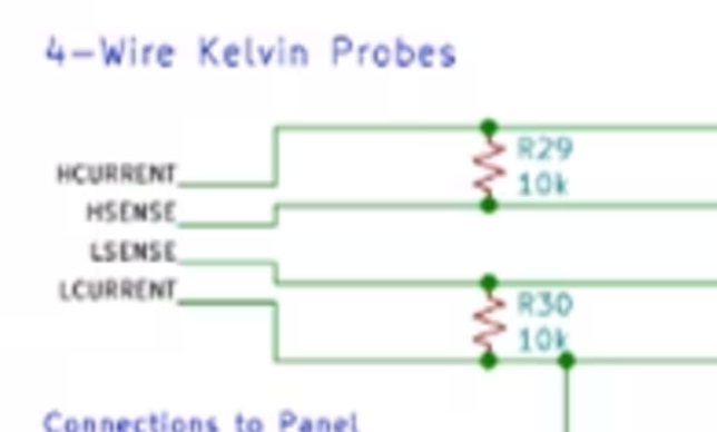
Note: there was some instability, but this is the solution; add two 10k resistors:

Meter Improvement (Conversion to Differential Input)
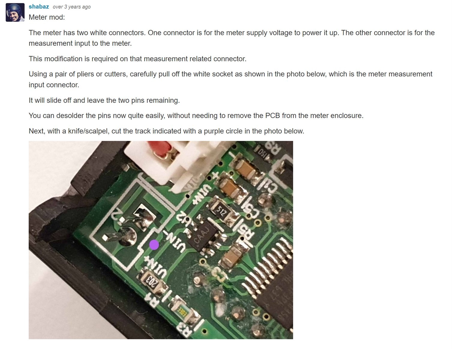
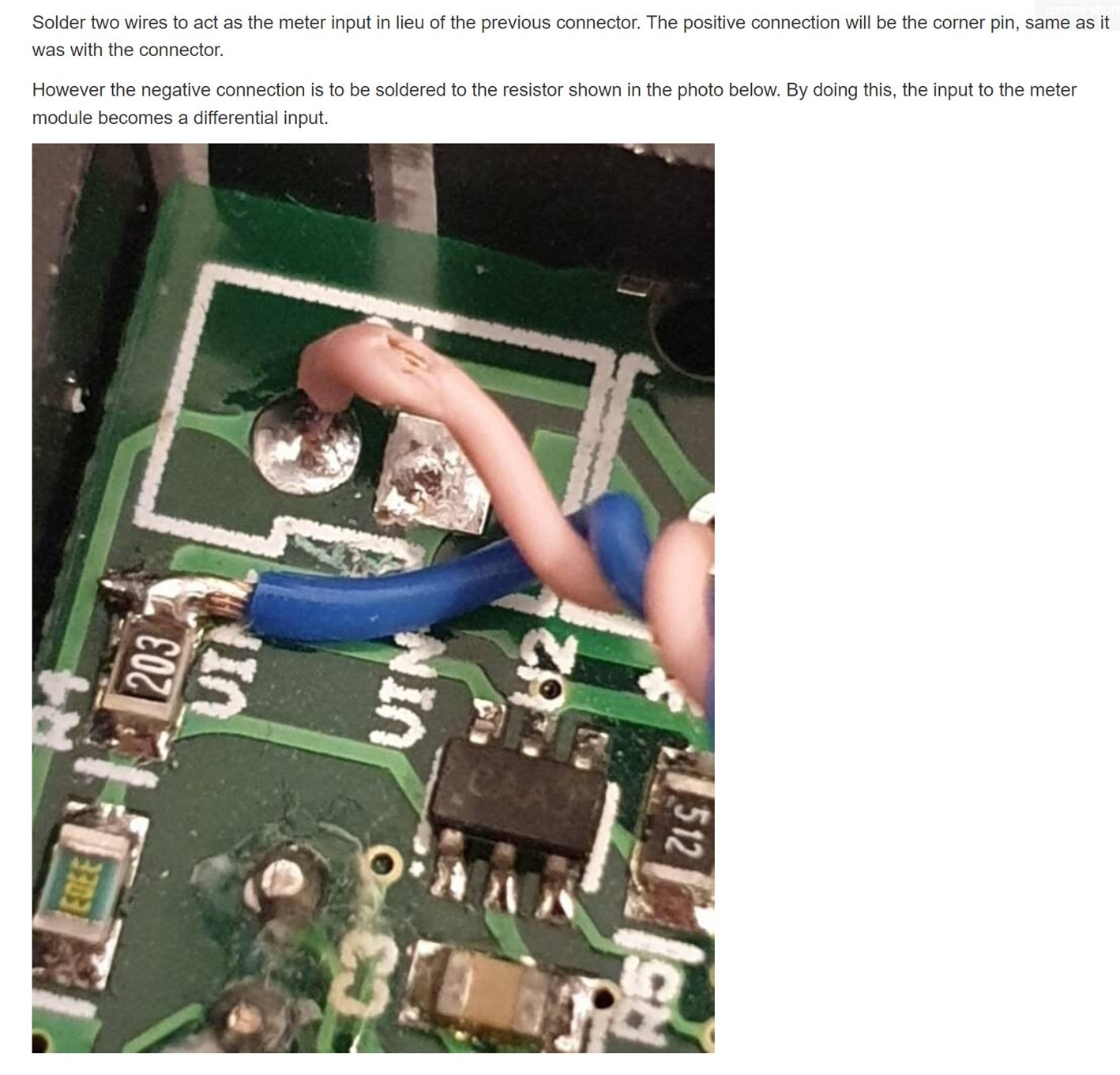
See the comments below PCB for a Kelvin (4-Wire) Milliohm Meter for some information about how the meter can be improved, to squeeze a bit more accuracy out of it. The information is reproduced here to make it easier to follow:


Bigger is Better?
After completing this build, I decided to start building another one, based on an interim board from Frank (it is not a version 2.0, more a version 1.5 of sorts).
This new one is broadly the same as the one described in this blog post, but with a slightly newer version of PCB. I put it in a bigger case, because I wish to eventually make this one battery powered. It is incomplete, I still need to add the battery power circuitry, and I need to drill the holes for the banana sockets.

A view inside the unit:

Summary
This is just a rev 1.0 project, but it is promising how accurate and stable it is, considering the low cost. It functions well.
It was a lot of fun to construct and try it out this Xmas! The design has a lot of flexibility, and is easy to solder and experiment with. I'm looking forward to seeing the design evolve - it will only improve I think!
I still can't get over how small it looks next to the other test instruments though : )
There is a rev 2 discussion here: New Improved DIY Milliohm Meter V2.0


Top Comments