- Introduction
- What is SDR?
- How Does it Work?
- Circuit Walk-Through
- Using It
- Printed Circuit Board
- Revision 1 PCB Issues and Fixes
- Parts List
- Summary
Introduction
I have never built a Software Defined Radio (SDR) before, so I decided to explore this topic briefly for this month's Project 14.
I was keen to explore Digital Signal Processing (DSP) and I wanted to have access to candidate signals for processing - so it seemed like a good idea to develop an SDR experimentation board that could provide not just access to useful signals for DSP, but furthermore, it could be used to explore other radio building blocks too.
This project has individual modules on the circuit board that can be constructed optionally, to gradually enhance the radio. Just one portion of the board needs to be constructed to have a functioning minimalist radio.
It turned out that building such a minimalist SDR can be quite simple (the components are large surface-mount parts). The minimal design requires zero hand-wound or adjustable components and worked the first time.
I always find wireless stuff fascinating, and this was a project that was as exciting to use as any beginner crystal radio project. In many ways, this is a far easier project because one can visually see the radio spectrum, whereas with a crystal set there was always a lot of guesswork despite there being so few components. Plus, all the parts are up-to-date and in production, unlike crystal sets which use near-obsolete variable capacitors, diodes, and so on. It makes me wonder why I didn't try to build such a SDR before. I have really enjoyed using this project in the short time I have had, and I'm looking forward to using it some more.
The fifteen-minute video here describes the project and then shows some sample radio station recordings captured with it.
What is SDR?
Software Defined Radio, as its name suggests, concerns radio capabilities that can be configured in software for any arbitrary modulation or demodulation schemes. A traditional radio might be designed for AM or FM for instance, and that's all it will do. In the case of SDR, the modulation can be modified in code, without requiring hardware modification. SDR can be attractive because it can allow for performance that could be extremely hard to achieve in hardware. SDR can also be a lower cost if the software is considered free (not always true of course).
It is possible to directly sample large portions of the RF spectrum, and then perform all operations digitally. However, such an SDR implementation can be expensive, and may even be problematic. There's also the problem of power consumption and computation resources.
Another method is to translate a portion of the RF spectrum to a particular, fixed frequency range (often a lower frequency range) known as the Intermediate Frequency (IF) and then sample the spectrum at that point. That's the approach that many SDRs take.
This project is broadly similar to many amateur radio (Ham) receiver projects. They all typically operate at a HF range (HF in this context usually means any frequency up to 30 MHz), down-converted to an IF that is around the 10 or 12 kHz range. This may sound strange, considering that 10-12 kHz is right in the centre of the audio spectrum (20 Hz to 20 kHz), however, the HF spectrum isn't normally used for high-quality music; it is used for speech mainly, and the bandwidth can be far lower (less than 10 kHz is common, sometimes even 2-3 kHz is acceptable). Mobile phones (at least old-school GSM anyway) do a similar thing of having such a low IF, although they have the IF set to zero Hz, and this allows low-cost, low-power ADC conversions despite the receive frequency being in the high hundreds of MHz. (Incidentally, zero-IF has its own complications, particularly that because the LO frequency is identical to the RF center frequency of interest, it can leak through to other parts of the system).
For this project, the reason for selecting a low IF in the 10-12 kHz range, is that it means that the analog-to-digital converter (ADC) can be a normal computer sound interface, and the 'software defined' capability can be PC software that captures the data stream from the sound interface, does the demodulation using digital signal processing (DSP) and outputs the result to the computer speaker.
As mentioned, all of the above is a very popular thing in the amateur radio world. I'm not a Ham (yet) so I'm merely following in other people's footsteps. This project will not have anywhere near the performance of other SDR projects I expect, however it is (I think) slightly simpler, since there are no coils to wind, and has a few differences since I didn't want to just copy a design, and I designed around the parts I had. There's plenty of scope for improvement since the differences are not necessarily better. Having said that, I was happy that the radio was able to pick up various shortwave stations, using a few meter length of wire as an antenna (I don't have any proper shortwave antenna to test with), and it worked the first time, so I think it's a design that could immediately provide results for anyone interested in building it. I think it could be useful for providing real-world signals for analog or digital processing, and experimenting with circuits.
How Does it Work?
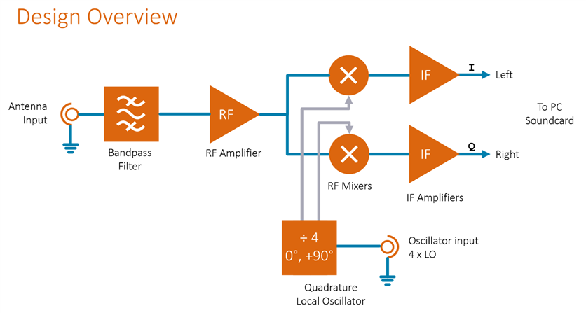
The diagram below shows the overall topology (for the minimalist implementation, the left side bandpass filter and RF amplifier are not required).
The way it works, is that the antenna picks up a mix of signals, and only the frequency band of interest is allowed to pass through a passive filter (LC filter), and then the filtered band is amplified. Next, frequency conversion is done to shift the RF frequency band into a lower band (known as the intermediate frequency or IF) centered around 12 kHz. At such a low IF, further amplification can be done using audio op-amps.
Mixers convert the RF input to an IF output by the rapid multiplication of the RF signal by a local oscillator (LO) input. The IF output includes the sum and difference of the LO and RF frequencies. For this SDR, the conversion to the IF occurs twice in parallel, using a 90-degree phase-shifted LO for one of the mixers.
Why are two signals, I and Q, better than one? After all, there are plenty of radio receivers that operate with a single, or single chain of mixers. The reasons are multiple, and nearly all relate to simplified procedures for signal processing. Furthermore, it allows for a far simpler front-end. Ordinarily, a filter is needed prior to the mixer, to get rid of the unwanted mixer output 'image frequency' which will overlay on the IF output. If a transmitter was broadcasting on the frequency that created such an image, it could swamp out the actual wanted signal. By having I and Q outputs, it is possible to mathematically remove the image frequency content, thus eliminating the need for good image rejection filters. The signal processing is simplified for all the popular modulation and demodulation methods. AM demodulation can simply* sum the recovered signal from the I and Q outputs. Single Side Band (SSB) demodulation can be achieved by either phase-shifting the recovered signal from one of the two outputs and then summing the signals, or by mixing digitally and then summing the two signals. Digital modulation methods that carry data in parallel across multiple different-phase carriers can have the data received and recovered by treating the I and Q signals as real and imaginary signals in the maths world, allowing a maths complex Fourier transform to be performed in DSP, for streams of recovered data bits to egress from the signal processing.
* In practice, for all of these methods, it is good to use the DSP capabilities as much as possible, to also try to correct for gain and phase errors from the upstream analog hardware, and to try and remove interfering signals if possible (various techniques to do this). The SDR software performs many tasks.
Fortunately, if desired, the maths and signal processing can be left to ready-made software (some is open source) running on the PC, without needing to do any hard work. However, for the experimenters, there are many possibilities; software exists to allow for algorithms to be tested. Free software to do this includes GNU Radio. Another approach could be to dispense with the PC and attach the I and Q outputs to a DSP chip.
Circuit Walk-Through
Voltage Regulators
Starting with the most generic bit, a 5V supply is needed for most of the circuitry. A 7805 integrated circuit is used to provide this; only about 20 mA is consumed and so a small 9V battery can be used, however, a large 1A capable 7805 was used since it's cheap, and can also support powering external DSP cards in the future. A 2.5V supply is required for op-amps, and that is generated using the TL431 IC. An alternative (better) option would be to use an op-amp to buffer half the voltage from the supply rail using a potential divider.
Quadrature Local Oscillator
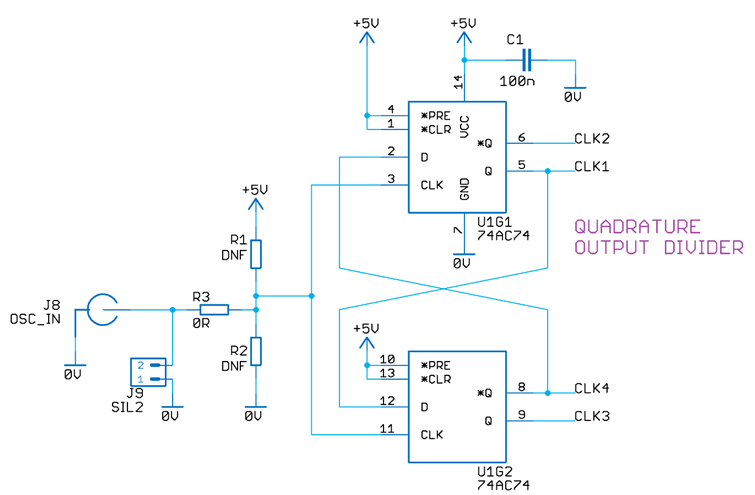
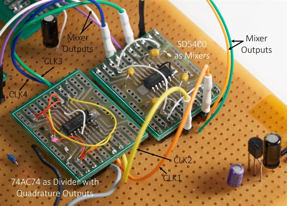
Two D-type flip-flops are connected together such that an input oscillator source can be frequency-divided by 4, with four outputs, each shifted by 90 degrees in phase. I copied this circuit, it's a very common way to generate quadrature signals, although it has the disadvantage that the oscillator needs to be 4 times the desired LO frequency. Another way to phase-shift could be to use a special transformer, called a Hybrid Coupler. More modern ways would be to use Direct Digital Synthesis (DDS) or dedicated clock generator ICs (Silicon Labs offer these) with in-built phase-shifted outputs. I didn't implement any oscillator or clock source to drive the dual flip-flops, because any function or signal generator can be used to provide that for test purposes (cheap DDS signal generators with keypad and display cost under $50 from Aliexpress). There are other lower-cost options too (see the comments section below, this project will be extended to include a low-cost frequency synthesizer with display and rotary encoder).
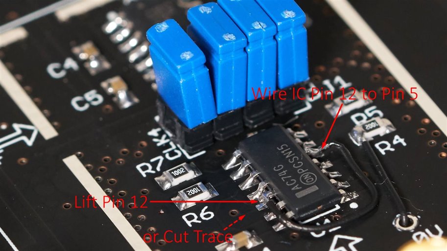
Note: The revision 1 PCB has a fault, where pin 12 of the 74AC74 was incorrectly connected to pin 6, instead of correct pin 5. The circuit diagram here is now correct. The revision 1 PCB requires pin 12 to be lifted and a bodge wire added to connect to pin 5. There's a photo further below showing how to do this. This will be resolved in a revision 2 PCB.
The oscillator signal is fed in from the coax connector J8, or jumper wires can be used connected to J9. Components R1, R2, and R3 can be modified to suit different oscillator connections.
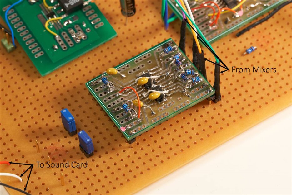
Mixers and IF Amplifiers
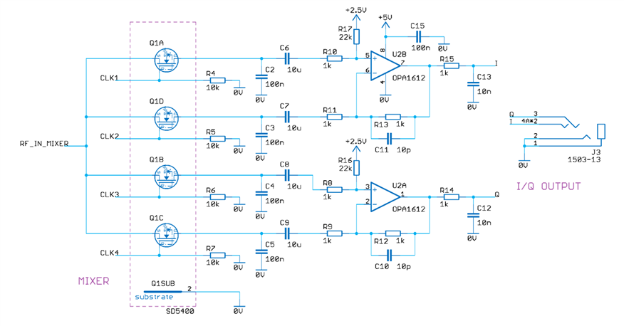
The mixer and amplifier circuits are shown together below. The circuit diagram looks busy but it's actually just two integrated circuits. Four FETs in one of the integrated circuits are used as analog switches, driven by the phase-shifted clocks. The SD5400 FET array IC that was used could be replaced by a different analog switch, but it needs to be able to switch at high speed (at least tens of MHz). Some projects online use the 74HC4066 IC, I didn't have this so I didn't try it and don't know how it compares (on paper the SD5400 should be better). Anyway, the SD5400 is still in production, although not many distributors sell it, Digikey do, at a very high price currently, and Future Electronics do too, at a very low price currently, in-stock, and also there are sources on eBay and Aliexpress, but they could be fake. I had purchased a few of them from Future Electronics a while back, so I know they are genuine. Other online projects use analog video switch ICs, which could be a good idea too. The SD5400 is fairly exotic but at least it's in stock, whereas a lot of more common ICs are out of stock currently.
Anyway, regardless of the analog switches used, the mixers are 'sampled data quadrature mixers', using output capacitors to sample-and-hold the level at switch-off, to both inputs of the op-amp, alternatively. There are many topologies possible. What's of concern is that the paths through both mixers should have the same delay, same gain and same frequency response. There's lots of scope to improve things here, for instance by better routing of signal paths, separated op-amps (instead of dual op-amps) for identical routing of signals, attempts at matching capacitors and resistors, and so on. For future experimentation! The selected dual op-amp is OPA1612, however, the footprint is very standard so other dual op-amps could be tried with the PCB too. A normal 3.5 mm stereo cable can be used to connect to the sound interface on the PC, with the I and Q outputs being the left and right channels respectively. For testing, I used an external USB sound device, but this is likely not necessary with the good quality sound inputs present in PCs these days.
At this stage, the minimalist implementation is complete, and free software (discussed further below in the 'Using It' section) can be downloaded to start using it : ) The 'antenna' can be a short length of wire connected to the RF_IN_MIXER connection in the circuit above.
RF Amplifier
I don't have a proper HF antenna and using a short length of wire might not pick up many radio stations. An RF amplifier can be prepended to the RF_IN_MIXER connection that was shown in the circuit above.
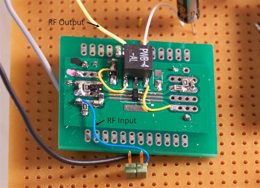
The amplifier circuit is near-identical to what was used for the PlanetCatcher project, except this time I wanted to avoid winding ferrite cores to keep the design simple. So, this time L1 happens to be a ready-made inductor in a standard easily available value from many manufacturers. In a similar vein, the output transformer T1 is an off-the-shelf ready-made transformer from Coilcraft that is easily available.
L1 and C20 act as a low-pass input filter. D1 provides some protection against high voltages. R23 and R24 provide quite a low DC bias on the output, merely to simplify driving the mixer. I'm sure most of this is not optimal, but it does work.
RF Filter
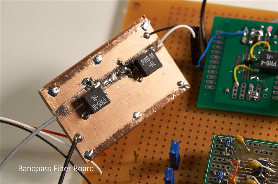
The RF filter required some guesswork and experimentation may improve it. I randomly chose 1:16 ratio transformers for at least a better match for any short wire antenna, and also so that the filter can have more sensible lower component values. The values below worked great for the AM broadcast band. Values would need to be adjusted for different HF bands. So far, I've disconnected the filter whenever I want to listen to the shortwave bands. For the future, another improvement would be to provide switching capability to select different filters.
Using It
A stereo cable is used to connect the board to the audio line input on a PC. The Mic input may work for some PCs too. An external sound card, such as a USB sound card, could be a better choice if it exists, especially if it has adjustable levels to prevent possible clipping. Another option is to just reduce the gain at the op-amps, or attach a stereo potentiometer to the output.
A couple of meters of wire is sufficient to act as an antenna, to pick up many radio stations.
The board was powered from a 9V PP3 battery. The oscillator input was connected to a signal generator set to Square Wave, 5V TTL-like output. For an ultra-cheap alternative, LTC1799 could be an option, controlled by a variable resistor.
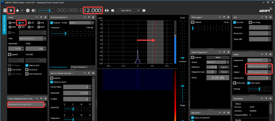
For the software side of things, I tried SDR Sharp and HDSDR. Although I liked the speed of HDSDR (it allows one to rapidly tune across the band, watching for spikes on the spectrum view), it had a couple of things I didn't like, and so for me, SDR Sharp ended up being the compromise.
The controls and displays in SDR Sharp are quite busy, but fortunately, it was easy enough to get going with it, despite not understanding what half the controls were for. The key things that need to be set are shown in red below. Drag the shaded spectrum segment to the right, such that 12.000 kHz is displayed at the top as shown in the screenshot. Once all these settings are configured, press the triangular play icon at the top-left, and you should start to see the spectrum appear, and the waterfall display, and hopefully noise! Adjust the signal generator frequency and you'll see the radio channel spikes move across the spectrum display, and centering on any of them should cause the audio to be successfully demodulated.
The actual frequency will be one quarter of the signal generator frequency (since the 74AC04 IC is used to divide by 4), and then subtract 12 kHz (that's the IF). In other words, received frequency = (signal generator frequency / 4) - 12k.
Printed Circuit Board
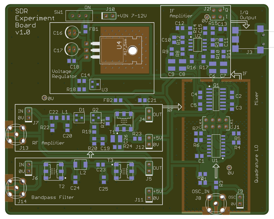
The Printed Circuit Board (PCB) files are attached to this blog post, ready for sending to factories such as JLC PCB, Elecrow, etc. The board size is 100 x 80 mm.
The layout as mentioned earlier is modular, and it has many connection points for probing signals or for tapping off signals for inserting amplifiers or filters.
I used large footprints (0805 sized or larger) for ease-of-soldering and future experimentation.
Revision 1 PCB Issues and Fixes
The photo below shows the fixes to two issues. One issue called Quadrature LO Pin 12 Issue is mandatory to fix. Without the fix, quadrature signals are not generated. The other fix, called Quadrature LO Isolating Capability is optional. Both of these issues will be resolved in a Revision 2 PCB.
Quadrature LO Pin 12 Issue
Note that the revision 1 PCB has a fault (described in the Quadrature Local Oscillator section above) where pin 12 of U1 (74AC74) needs to be lifted off the PCB, and then that pin 12 on the IC needs to be wired to pin 5. Without this fix, the symptoms are that quadrature signals will not be generated, and just divide-by-2 will occur.
Quadrature LO Isolating Capability
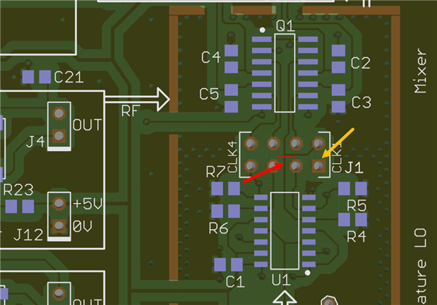
The other wire shown in the photo above (connected to resistor R4) is a fix that is only needed if it is desired to be able to fully isolate all the quadrature signals using the four blue jumpers in the photo. The comments below describe that issue and the fix in detail, but in brief, the fix is:
(1) Cut the trace shown in red in the photo below.
(2) Connect Pin 5 of U1 (74AC74) to the pin marked in yellow (connector J1, square pad pin). The easiest way to do that, is to connect a wire from the left side of R4, through a 0V test hole (wire needs insulation) and then solder to the square pad pin on the underside of the board.
Parts List
All parts are currently available from Farnell/Newark, with the exception of SD5400CY which is currently available from Future Electronics.
| Qty | Value | Device | Identifier |
|---|---|---|---|
| 1 | 0R | 0805 Resistor | R3 |
| 2 | 100R | 0805 Resistor | R20, R24 |
| 2 | 100k | 0805 Resistor | R21, R22 |
| 4 | 10k | 0805 Resistor | R4, R5, R6, R7 |
| 10 | 1k | 0805 Resistor | R8, R9, R10, R11, R12, R13, R14, R15, R18, R23 |
| 2 | 22k | 0805 Resistor | R16, R17 |
| 1 | 27R | 0805 Resistor | R19 |
| 9 | 100n | 0805 Capacitor | C1, C2, C3, C4, C5, C15, C18, C19, C21 |
| 3 | 10n | 0805 Capacitor | C12, C13, C14 |
| 2 | 10p | 0805 Capacitor | C10, C11 |
| 1 | 15n | 0805 Capacitor | C23 |
| 1 | 1n | 0805 Capacitor | C22 |
| 1 | 22p | 0805 Capacitor | C20 |
| 2 | 3.3n | 0805 Capacitor | C24, C25 |
| 5 | 10u | 1210 Capacitor | C6, C7, C8, C9, C26 |
| 1 | 2.2u | 16V Electrolytic Cap. 4-5mm dia | C17 |
| 1 | 22u | 16V Electrolytic Cap. 4-5mm dia | C16 |
| 1 | 470nH | 0805 Inductor | L1 |
| 1 | 4.7uH | 1812 Inductor | L2 |
| 2 | FB-0805 | 0805 Ferrite Bead, example: Laird HZ0805E601R-10HZ0805E601R-10 | FB1, FB2 |
| 1 | PWB-4-AL | 1:4 Transformer CoilCraft PWB-4-AL | T1 |
| 2 | PWB-16-AL | 1:16 Transformer CoilCraft PWB-16-AL | T2, T3 |
| 1 | BAV99 | BAV99 Dual Diode SOT-23 | D1 |
| 1 | MMBFJ310 | JFET MMBFJ310 SOT-23 | Q2 |
| 1 | TL431ACDBZTTL431ACDBZT | Voltage Ref. TL431 SOT-23 | U3 |
| 1 | LM7805 | 7805 5V Regulator TO-220 | U4 |
| 1 | 74AC74 | SOIC CD74AC74 Dual Flip-Flop | U1 |
| 1 | SD5400CY | SOIC Quad FET SD5400CY | Q1 |
| 1 | OPA1612 | SOIC Dual Op-Amp OPA1612 | U2 |
| 1 | SMA Conn. | SMA Connector Thru-Hole or Edge | J8 |
| 1 | 1503-13 | Lumberg 1503-13 Jack Socket | J3 |
| 1 | SPDT | SPDT 09.03201.0209.03201.02 EOZ 2.54mm pitch pins | SW1 |
| 1 | PP3 Clip | PP3 Battery Clip wire-ended | J10 |
| 1 | Cable | 3.5mm Stereo Audio Plug Cable | N/A |
Summary
With just a few components it was possible to really begin to explore both from the technical perspective of radio and digital signal processing, but also from the pleasure of seeking out interesting radio stations perspective too. It was extremely surprising to me that no tweaking effort was needed to get it to immediately function, leaving time to explore with amplifiers and filters to improve things.
I'm keen to build up the circuit again properly on the PCB, and spend time using it, and hopefully expanding on it.
I hope this blog post was useful, and I'm glad that both Element 14 and Project 14 give us the opportunities to explore interesting topics.
Finally, for the shortwave radio stations that were in the video, the audio recordings are on Github in uncompressed WAV format, in case anyone is interested to do anything with such sample audio.
Thanks for reading!






Top Comments
-

Jan Cumps
-
Cancel
-
Vote Up
0
Vote Down
-
-
Sign in to reply
-
More
-
Cancel
-

shabaz
in reply to Jan Cumps
-
Cancel
-
Vote Up
0
Vote Down
-
-
Sign in to reply
-
More
-
Cancel
-

Jan Cumps
in reply to shabaz
-
Cancel
-
Vote Up
0
Vote Down
-
-
Sign in to reply
-
More
-
Cancel
-

Jan Cumps
in reply to Jan Cumps
-
Cancel
-
Vote Up
0
Vote Down
-
-
Sign in to reply
-
More
-
Cancel
Comment-

Jan Cumps
in reply to Jan Cumps
-
Cancel
-
Vote Up
0
Vote Down
-
-
Sign in to reply
-
More
-
Cancel
Children