element14 Community
element14 Community
    Register Log In
  • Site
  • Search
  • Log In Register
  • About Us
  • Community Hub
    Community Hub
    • What's New on element14
    • Feedback and Support
    • Benefits of Membership
    • Personal Blogs
    • Members Area
    • Achievement Levels
  • Learn
    Learn
    • Ask an Expert
    • eBooks
    • element14 presents
    • Learning Center
    • Tech Spotlight
    • STEM Academy
    • Webinars, Training and Events
    • Learning Groups
  • Technologies
    Technologies
    • 3D Printing
    • FPGA
    • Industrial Automation
    • Internet of Things
    • Power & Energy
    • Sensors
    • Technology Groups
  • Challenges & Projects
    Challenges & Projects
    • Design Challenges
    • element14 presents Projects
    • Project14
    • Arduino Projects
    • Raspberry Pi Projects
    • Project Groups
  • Products
    Products
    • Arduino
    • Avnet Boards Community
    • Dev Tools
    • Manufacturers
    • Multicomp Pro
    • Product Groups
    • Raspberry Pi
    • RoadTests & Reviews
  • Store
    Store
    • Visit Your Store
    • Choose another store...
      • Europe
      •  Austria (German)
      •  Belgium (Dutch, French)
      •  Bulgaria (Bulgarian)
      •  Czech Republic (Czech)
      •  Denmark (Danish)
      •  Estonia (Estonian)
      •  Finland (Finnish)
      •  France (French)
      •  Germany (German)
      •  Hungary (Hungarian)
      •  Ireland
      •  Israel
      •  Italy (Italian)
      •  Latvia (Latvian)
      •  
      •  Lithuania (Lithuanian)
      •  Netherlands (Dutch)
      •  Norway (Norwegian)
      •  Poland (Polish)
      •  Portugal (Portuguese)
      •  Romania (Romanian)
      •  Russia (Russian)
      •  Slovakia (Slovak)
      •  Slovenia (Slovenian)
      •  Spain (Spanish)
      •  Sweden (Swedish)
      •  Switzerland(German, French)
      •  Turkey (Turkish)
      •  United Kingdom
      • Asia Pacific
      •  Australia
      •  China
      •  Hong Kong
      •  India
      •  Korea (Korean)
      •  Malaysia
      •  New Zealand
      •  Philippines
      •  Singapore
      •  Taiwan
      •  Thailand (Thai)
      • Americas
      •  Brazil (Portuguese)
      •  Canada
      •  Mexico (Spanish)
      •  United States
      Can't find the country/region you're looking for? Visit our export site or find a local distributor.
  • Translate
  • Profile
  • Settings
Smart Alarm Clock
  • Challenges & Projects
  • Project14
  • Smart Alarm Clock
  • More
  • Cancel
Smart Alarm Clock
Blog Tempus Fugit... Part 3: micro:bit Interfacing 5V Logic
  • Blog
  • Forum
  • Documents
  • Events
  • Polls
  • Files
  • Members
  • Mentions
  • Sub-Groups
  • Tags
  • More
  • Cancel
  • New
Join Smart Alarm Clock to participate - click to join for free!
  • Share
  • More
  • Cancel
Group Actions
  • Group RSS
  • More
  • Cancel
Engagement
  • Author Author: balearicdynamics
  • Date Created: 25 Jul 2018 10:14 PM Date Created
  • Views 4202 views
  • Likes 9 likes
  • Comments 9 comments
  • transistor
  • display controller
  • vintage
  • advanced micro:bit projects
  • microbit projects
  • smartalarmch
  • 7 segment display
  • microbit
  • smartalarmclockch
  • micro bit
  • advanced_microbit_projects
  • digital clock
  • alarm clock
  • open collector
  • smart clock
  • step up
Related
Recommended

Tempus Fugit... Part 3: micro:bit Interfacing 5V Logic

balearicdynamics
balearicdynamics
25 Jul 2018
    • Introduction
    • Providing 5V Extra Power
    • Interfacing 3V Logic to 5V Logic
      • micro:bit Output Pin
      • Open Collector Output Pin
    • The Other Parts

Introduction

To control the 7-segments LCD display with the micro:bit the easiest way I found is using a dedicated IC, controllable through the SPI protocol. The problem is that both the display module (4 digits) and the IC works both at 5V. So, the problems are two: make available a second power line at 5V while the micro:bit just provide 3.3V and interface the three pins MISO, MOSI and SCK of the SPI protocol between the micro:bit (3.3V) and the display controller IC (5V).

In this part we will see how these two issues can be solved easily with a simple hack to the BBC micro:bit


Providing 5V Extra Power

Two assumption can help us to depict a better scenario: the BBC micro:bit is an open source platform and is powered with a USB - we assume that it is powered by - cable.The software firmware and hardware schematics are available for free on the micro:bit GitHub repository and the full schematics of the board is in attach to this post.

image

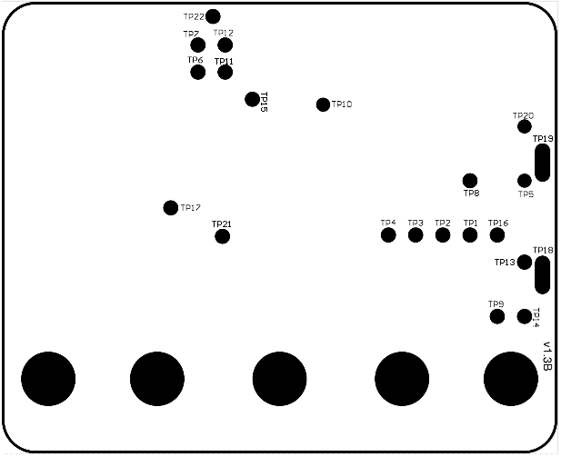
The above image shows one of the page of the attached board schematics. As you can see there are here and there a series of test points, those round contacts you can find to the back of the micro:bit board, as shown in the image below.

image

One of the test points corresponds to the 5V from the USB connector. Unfortunately there is not a detailed description where the test point mentioned on the schematics are positioned on the board PCB. Digging a while on the net I have found a useful documentation page on Stack Exchange, Electrical Engineering .To make the things easier I have put the map below, as well as the meaning of every test point.

image

1 TMS -- Debug interface for KL26
2 TDO -- "
3 TDI -- "
4 TCLK -- "
5 RST* -- "
6 TGT_SWDIO
7 TGT_SWCLK
8 KL26 XTAL -- has 16MHz sine wave
9 GND
10 VBUS_IF -- carries 5V when USB plugged in
11 USB-D+
12 USB-D-
13 VBAT
14 +V_TGT
15 TGT_TX -- UART transmit from nRF51
16 +3.3V_IF
17 TGT_RX -- UART receive from nRF51
18 VBAT
19 GND
20 TGT_RESET
21 GND
22 GND


We are interested to the TestPoint 10m VBUS_IF providing 5V from USB. Note that when the BBC is not powered through the USB but only the battery there is no power on this TestPoint. So, the extra 5V power is easily obtained soldering a wire on the TP10 as shown in the image below.

image

Interfacing 3V Logic to 5V Logic

Interfacing the two votlage level logic remain the last issue. Initially I though to find some step-up circuit but the solution seemed me too complex for this kind of application. As a matter of fact, all what we need is to convert the GPIO output signal to an open collector. The handwritten schematics below shows ow it is easy to do this with an NPN transisotor and a couple of resistors.


image

The bottom circuit uses a single transistor - a BC547 ior PN2222 are fine - but the signal of the open collector is the negated output of the originating micro:bit pin. To avoid problems I have used a second transistor (as a matter of fact the circuit has been replicated) to invert the logic again.

imageimage

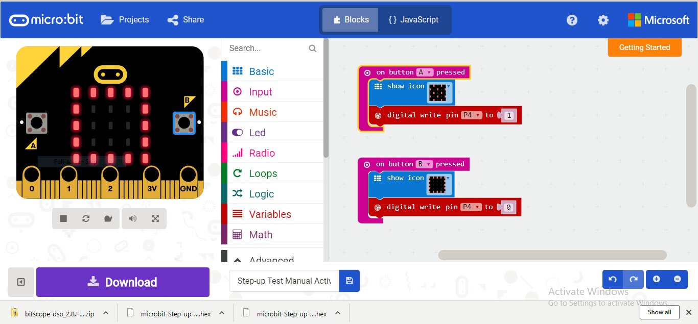
The two images above test with a blinking LED the coherence of the logic levels with a very easy program created with Java Blocks

image

You don't have permission to edit metadata of this video.
Edit media
x
image
Upload Preview
image


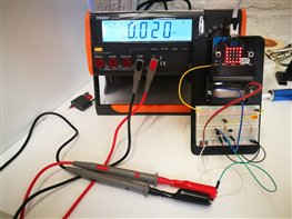
The two images below shows the voltage levels for low and high output on the 5V open collector inverted signal.

imageimage

Writing another sort program on the micro:bit I have created an automatic i/0 infinite loop output to test the functionality at higher frequencies; I have also included some output to the micro:bit LED matrix to introduce some random delay in the output. In fact, using the GPIO pins that are connected to the LED matrix it is expected that the display should be deactivated just to avoid this effect.

image

Testing the inverted open collector output and the micro:bit corresponding GPIO pin the signals demonstrated working perfectly.


micro:bit Output Pin

image

Open Collector Output Pin

image

It is time to test the 7-segments display controller!


The Other Parts

Tempus Fugit... Part 1: 1978 a.d.

Tempus Fugit... Part 2: 2018 a.d.

Tempus Fugit... Part 4: micro:bit 5V SPI

Attachments:
image SCH_BBC-Microbit_V1.3B.pdf
  • Sign in to reply

Top Comments

  • luislabmo
    luislabmo over 7 years ago +4
    Hello balearicdynamics , it is nice to keep the suspense going.... Luis
  • balearicdynamics
    balearicdynamics over 7 years ago in reply to luislabmo +4
    Lol Luis! Yesterday night I pressed the dn publish button then it was too late to repair... A bit of suspence and things will be unvealed soon Enrico
  • shabaz
    shabaz over 7 years ago +3
    Hi Enrico, Excellent, detailed post! Thank you for this, I'd not seen such comprehensive information on the micro:bit hardware - I did not realize the schematics were available. Also all the valuable detail…
Parents
  • DAB
    DAB over 7 years ago

    Yes, transistors are your friend.


    I had to use a transistor to boost the current of a RPi to drive a circuit. Simple solutions are always the best.


    DAB

    • Cancel
    • Vote Up +1 Vote Down
    • Sign in to reply
    • More
    • Cancel
  • balearicdynamics
    balearicdynamics over 7 years ago in reply to DAB

    Maybe I born with transistors and NE555 but if those discrete components are evolved during tenth or years and are still alive there will be a reason...


    Then, I agree that simple solutions are always the best. Cheap and working. I have finished yesterday night the three pin (SPI connection) circuit and just trying with a stupid delay program the result was surprisingly (at least for me).  I am about to publish a next step on this part. Stay in touch image


    Enrico

    • Cancel
    • Vote Up +1 Vote Down
    • Sign in to reply
    • More
    • Cancel
Comment
  • balearicdynamics
    balearicdynamics over 7 years ago in reply to DAB

    Maybe I born with transistors and NE555 but if those discrete components are evolved during tenth or years and are still alive there will be a reason...


    Then, I agree that simple solutions are always the best. Cheap and working. I have finished yesterday night the three pin (SPI connection) circuit and just trying with a stupid delay program the result was surprisingly (at least for me).  I am about to publish a next step on this part. Stay in touch image


    Enrico

    • Cancel
    • Vote Up +1 Vote Down
    • Sign in to reply
    • More
    • Cancel
Children
No Data
element14 Community

element14 is the first online community specifically for engineers. Connect with your peers and get expert answers to your questions.

  • Members
  • Learn
  • Technologies
  • Challenges & Projects
  • Products
  • Store
  • About Us
  • Feedback & Support
  • FAQs
  • Terms of Use
  • Privacy Policy
  • Legal and Copyright Notices
  • Sitemap
  • Cookies

An Avnet Company © 2025 Premier Farnell Limited. All Rights Reserved.

Premier Farnell Ltd, registered in England and Wales (no 00876412), registered office: Farnell House, Forge Lane, Leeds LS12 2NE.

ICP 备案号 10220084.

Follow element14

  • X
  • Facebook
  • linkedin
  • YouTube