


 | Enter Your Electronics & Design Project for a chance to win a Grand Prize for Originality, a Tool Set, and a $100 Shopping Cart! | Project14 Home |
| Monthly Themes | ||
| Monthly Theme Poll |

Blog posts:
This is part 1
"No lies" IR Thermometer - part II
"No lies" IR Thermometer - part III
"No lies" IR Thermometer - part IV
Introduction
I like thermometers. Temperature is probably the most popular quantity to be measured at our homes, work places, in machines etc. When me and my wife were expecting a future electronics enthusiast, I decided to give him or her (we wanted to be surprised) a body thermometer. By that time, I tried two commercially available thermometers (for body temperature measurements) and had two issues with it. First, there is no value specified for the emissivity set in the IR sensor. Second, there are usually two types of measurements: for body use and general-purpose home use. The trouble is, manufacturers don’t even care to say, what is the difference. Just use the “head” symbol for body and a “house” for the rest of the universe. The head symbol outputs 37 Centigrade for anything between 34-35 Centigrade surface temperature.
I am not an engineer, but I know that a value of any quantity is useless without the tolerance specified. That is why I decided to build an IR thermometer myself, using “no lies” technology. To know what is directly measured, what is the tolerance and do not add some invisible magic math to it. We mainly wanted to measure body temperature and temperature of water / glass during cooking or preparing meals for our child. And for preparing the best bath ever 
I also wanted to try to get my first PCB manufactured by a professional company. I previously made a few PCBs using photo etching, but I believe that time is gone and there is not much sense in manufacturing PCBs at home any more. But let's take one step at a time...
IR thermometer’s theory
Just a brief explanation: an infrared thermometer measures the amount of thermal radiation by the object being measured. It is based on an effect called black-body radiation, which is a thermal electromagnetic radiation, that has a specific spectrum and intensity, depending on the body’s temperature. Most of the emission is in the infrared region, but with increasing temperature get to the human visible light region.
To make things more complicated, real objects never radiate as ideal black-bodies. They emit a fraction of what would the ideal black-body emit. This is described as emissivity, meaning how well the real body radiates, compared to the black body. Emissivity also depends on various factors, but in common engineering, it is considered a constant.
I will forward more interested readers to Wikipedia with a few well described articles:
https://en.wikipedia.org/wiki/Infrared_thermometer
https://en.wikipedia.org/wiki/Black-body_radiation
https://en.wikipedia.org/wiki/Emissivity
Common IR thermometers measure only in the infrared spectrum, because we are talking about temperatures from ca. -30 Centigrade to +300 Centigrade. The thermometers are characterized by temperature range, accuracy, angular coverage, distance to spot ratio and more.
Building the thermometer
I like an iterative approach to build things. It usually works better for me to start with smaller steps, slowly but steadily, instead of spending too much time planning and actually not getting to the construction phase. I like things to be perfect, but in real life, things just “good enough” are the ones that sell the most.
The sensor

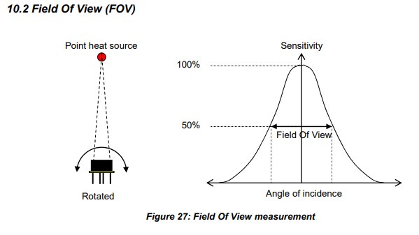
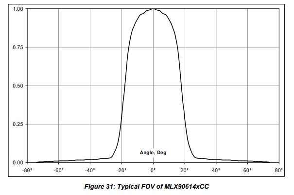
The key component for the thermometer is obviously the IR sensor. I stumbled upon MLX90614 from Melexis and ordered one. It is a factory calibrated sensor that can measure both sensor (ambient) temperature: -40 to +125 Centigrade and object temperature using an IR sensitive thermopile detector chip: -70 to +380 Centigrade, with resolution of 0,02 Centigrade. Specifically, I chose MLX90614ESF-DCC-000, which is a recommended part for medical applications. This simply means an improved accuracy in the range of 16 to 40 Centigrade. The following pictures are extracted from the datasheet:


It is also important to mention a field of view (FOV), which is 35° for my part number (the cheapest variants have 90°) and therefore distance to spot ratio of 1:1 (the maximum you can get is ca. 2:1 to 2.5:1 with DCI variant, featuring a FOV of only 5°).
The sensor can tell the object temperature over SMBus or measuring the PWM duty cycle. I chose the SMBus, because PWM requires accurate measurement using timers etc.
The microcontroller
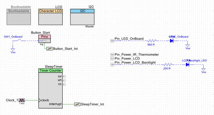
I knew I need to measure and display ambient and object temperature, so I grabbed a PSoC5LP kit without much thinking. It features a prototyping area, LCD and possibility to run on 3.3 V (including the LCD).
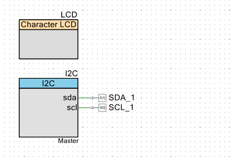
HW schematics in PSoC Creator was simple:
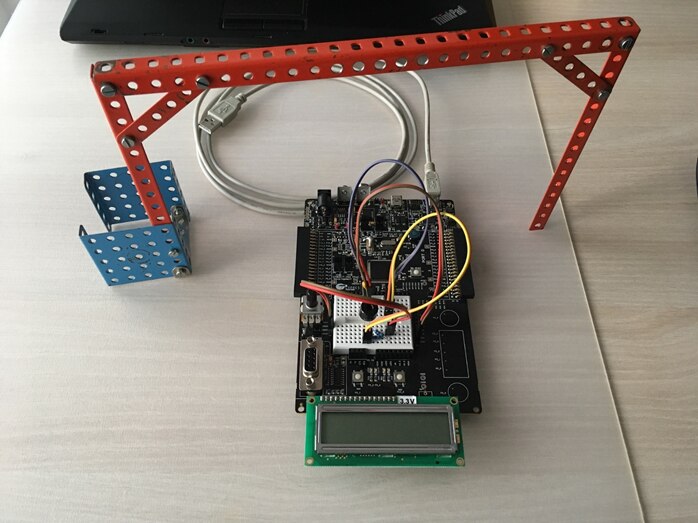
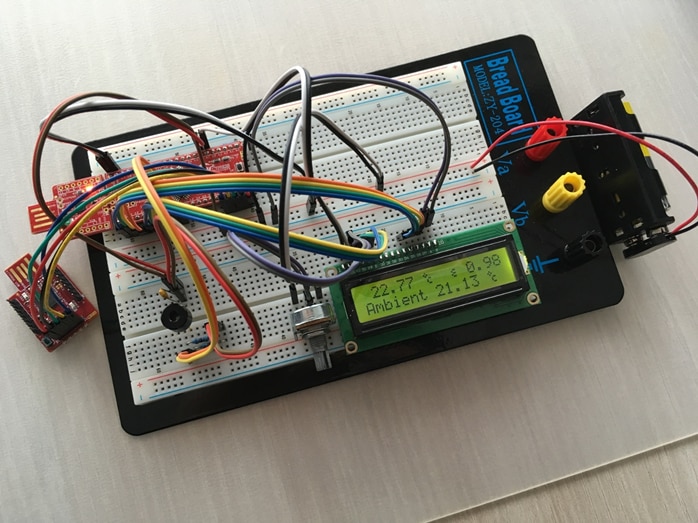
And a prototype:
(Note: the metal built gate is not relevant to this project.)
The procedure
The first thing to learn was how to handle an SMBus sensor. It is not complicated, but what helped a lot was an application note from Maxim, mentioning the key differences between I2C and SMBus. The good thing is that I2C microcontroller peripheral can be used. However, there is a timeout between commands, which means you can’t debug the bus between request and response commands, just after a complete transmission. My favourite way of starting with sensors is connecting them to a logic analyzer and sending one command at a time. This is perfectly OK with I2C sensors, but not with SMBus.
Also, there is an SMBus speciality called Packet Error Check (PEC), which is an CRC-8 attached to every command and read data. I found tones of code from various developers online, but most of the people working with SMBus sensors only read the data, thus ignoring the PEC. Only people who need to write some data (configuration etc.) need to learn how to implement the CRC-8 generator. I even found some examples using fixed CRCs calculated for some specific commands. One of my future goals is to change the sensor emissivity on the fly, which requires actual calculation in program code. I found great help in TI’s application note for a completely different processor, but with code usable after a few adjustments for my purposes. In addition to that, I have to recommend reading a Painless guide to CRC error detection algorithms by Ross N. Williams. Written 25 years ago, but still valid and super useful.
After getting the correct data from the sensor, I realized PSoC 5 is an overkill. So instead of a $20 microcontroller, I chose a $4 PSoC 4, that is available on the cheapest PSoC 4 kit (also $4): http://www.cypress.com/documentation/development-kitsboards/psoc-4-cy8ckit-049-4xxx-prototyping-kits This kit doesn’t have an onboard debugger, only an USB to UART/I2C/custom converter, but this issue can be resolved using a $10 kit with KitProg2. One modification (removing a diode) is needed on the programmer, so the USB doesn’t fry the 3,3 V sensor.
More features were added to the second prototype: backlit LCD, state machine code with a timer used to let the microcontroller sleep after a measurement and emissivity was displayed on the LCD. The design was made with low power in mind and the requirement was to completely switch off parts of the circuit that are not in use. This resulted in powering everything through GPIO pins: LCD, LCD backlight and the IR thermometer sensor.
HW schematics in PSoC Creator:
And the second prototype:
TO BE CONTINUED...
David
Top Comments