element14 Community
element14 Community
    Register Log In
  • Site
  • Search
  • Log In Register
  • About Us
  • Community Hub
    Community Hub
    • What's New on element14
    • Feedback and Support
    • Benefits of Membership
    • Personal Blogs
    • Members Area
    • Achievement Levels
  • Learn
    Learn
    • Ask an Expert
    • eBooks
    • element14 presents
    • Learning Center
    • Tech Spotlight
    • STEM Academy
    • Webinars, Training and Events
    • Learning Groups
  • Technologies
    Technologies
    • 3D Printing
    • FPGA
    • Industrial Automation
    • Internet of Things
    • Power & Energy
    • Sensors
    • Technology Groups
  • Challenges & Projects
    Challenges & Projects
    • Design Challenges
    • element14 presents Projects
    • Project14
    • Arduino Projects
    • Raspberry Pi Projects
    • Project Groups
  • Products
    Products
    • Arduino
    • Avnet Boards Community
    • Dev Tools
    • Manufacturers
    • Multicomp Pro
    • Product Groups
    • Raspberry Pi
    • RoadTests & Reviews
  • Store
    Store
    • Visit Your Store
    • Choose another store...
      • Europe
      •  Austria (German)
      •  Belgium (Dutch, French)
      •  Bulgaria (Bulgarian)
      •  Czech Republic (Czech)
      •  Denmark (Danish)
      •  Estonia (Estonian)
      •  Finland (Finnish)
      •  France (French)
      •  Germany (German)
      •  Hungary (Hungarian)
      •  Ireland
      •  Israel
      •  Italy (Italian)
      •  Latvia (Latvian)
      •  
      •  Lithuania (Lithuanian)
      •  Netherlands (Dutch)
      •  Norway (Norwegian)
      •  Poland (Polish)
      •  Portugal (Portuguese)
      •  Romania (Romanian)
      •  Russia (Russian)
      •  Slovakia (Slovak)
      •  Slovenia (Slovenian)
      •  Spain (Spanish)
      •  Sweden (Swedish)
      •  Switzerland(German, French)
      •  Turkey (Turkish)
      •  United Kingdom
      • Asia Pacific
      •  Australia
      •  China
      •  Hong Kong
      •  India
      •  Korea (Korean)
      •  Malaysia
      •  New Zealand
      •  Philippines
      •  Singapore
      •  Taiwan
      •  Thailand (Thai)
      • Americas
      •  Brazil (Portuguese)
      •  Canada
      •  Mexico (Spanish)
      •  United States
      Can't find the country/region you're looking for? Visit our export site or find a local distributor.
  • Translate
  • Profile
  • Settings
Test Instrumentation
  • Challenges & Projects
  • Project14
  • Test Instrumentation
  • More
  • Cancel
Test Instrumentation
Blog "No lies" IR Thermometer - part IV
  • Blog
  • Forum
  • Documents
  • Events
  • Polls
  • Files
  • Members
  • Mentions
  • Sub-Groups
  • Tags
  • More
  • Cancel
  • New
Join Test Instrumentation to participate - click to join for free!
  • Share
  • More
  • Cancel
Group Actions
  • Group RSS
  • More
  • Cancel
Engagement
  • Author Author: koudelad
  • Date Created: 11 Oct 2018 5:39 PM Date Created
  • Views 2248 views
  • Likes 11 likes
  • Comments 9 comments
  • ir_thermometer
  • psoc 4
  • diytestinstruch
Related
Recommended

"No lies" IR Thermometer - part IV

koudelad
koudelad
11 Oct 2018
image

Test Instrumentation

Enter Your Electronics & Design Project for a chance to win a Grand Prize for Originality, a Tool Set, and a $100 Shopping Cart!

Back to The Project14 homepage image

Project14 Home
Monthly Themes
Monthly Theme Poll


Links to previous blog posts:

"No lies" IR Thermometer - part I

"No lies" IR Thermometer - part II

"No lies" IR Thermometer - part III

This is part IV


I have described and showed the custom built IR thermometer so far. It doesn't look perfect, but does the job. We use it every day at home, especially for the baby related measurements.

After I built the first prototype I realized that many aspects of it could be improved. This is a perfect opportunity to perform another iteration.


What can be improved

I gathered a list of requirements:

  • Design that could be integrated into a box easier. Building a prototype is one thing, but making something that looks like a product is a completely different story.
  • Device that would better fit into hand and not covering the measured object that much. Make it a bit smaller, use smaller batteries
  • Unify the component size. The first revision used both 1206 and 0805 components. It is not a good idea to maintain stock of multiple sizes.
  • Reverse polarity protection. At first, I used locking connectors for the battery holder connection: https://uk.farnell.com/wurth-elektronik/61900211121/header-2-54mm-locking-2way/dp/1841369?st=connector%202,54%20locking. However, I had to change it to a non-locking type, because the two pin variant was very loose. I haven't seen such a bad connection for the famous 3 or 4-pin computer fan cables.
  • Remove unnecessary components.
  • Have the possibility to use MLX90614 in TO-39 can, but also MLX90615 in TO-46 can. I got some MLX90615 from a friend. Here is a comparision sheet for those, who are interested: https://www.melexis.com/-/media/files/documents/product-flyers/quick-reference-infrared-temperature-sensors.pdf


IR thermometer - revision B

All the mentioned requirements led me to creating a next revision.


First of all, here is the schematics. I wanted to make it more pretty this time, because the last one was just a wiring mess.

image


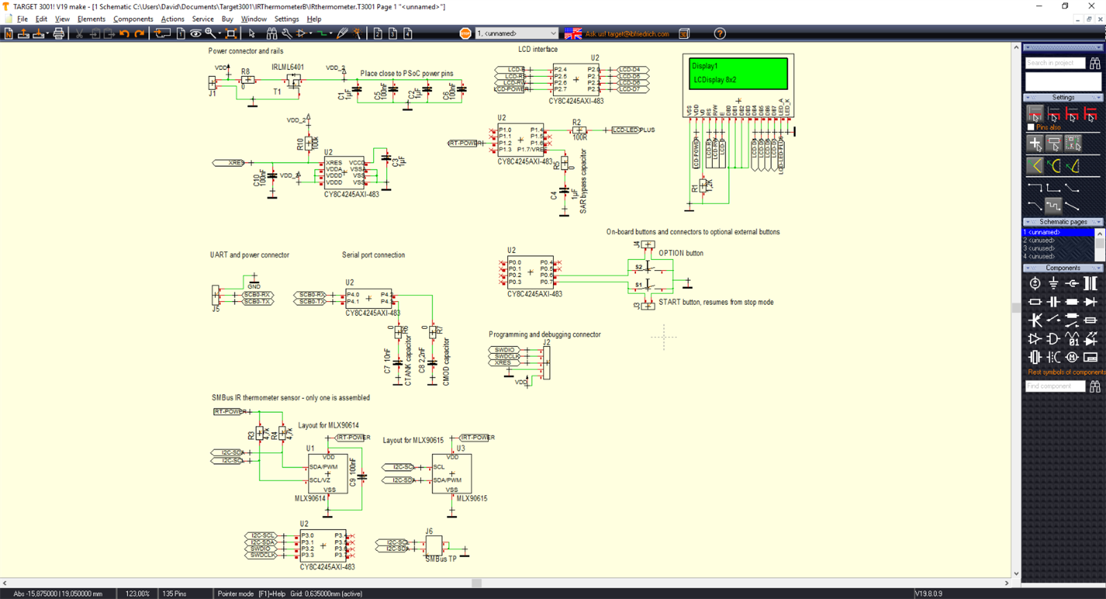
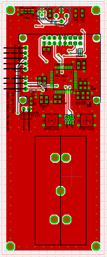
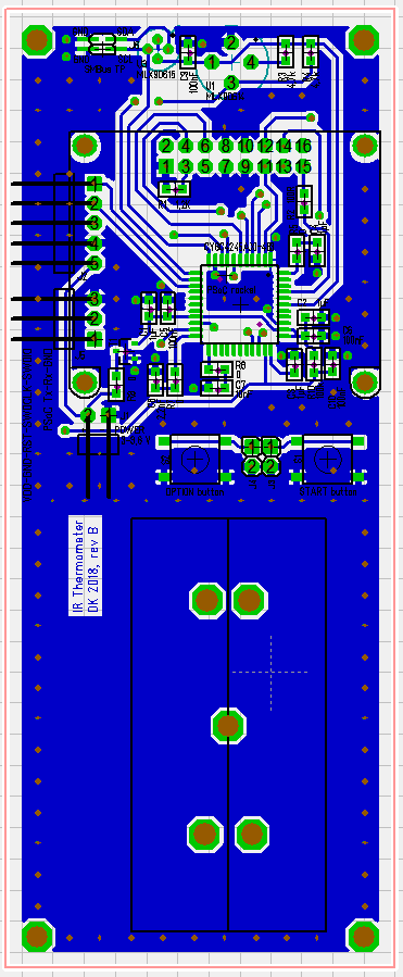
The schematics was then translated into a completely new PCB design.

imageimage


What is new

  • Mounting holes in the corners. I haven't decided yet, whether to make my own box or use an existing one (at this point I guess the choice is limited, so I will have to somehow create something myself).
  • Place for battery pack holder with mounting holes.
  • Removed unnecessary LED from the first revision.
  • PCB adjusted for using one or even two thermometer sensors at a time (they have different SMBus address).
  • Design is more "remote control" like to fit better in the hand.
  • Display 8x2 characters instead of 16x2.
  • Debug connector for SMBus, just to have the possibility to externally debug the bus.
  • All capacitors and resistors are 0805 size.
  • Ground planes on both copper top and bottom layers. Connected using many vias.
  • Better filtering capacitors PCB layout to eliminate ground loops.
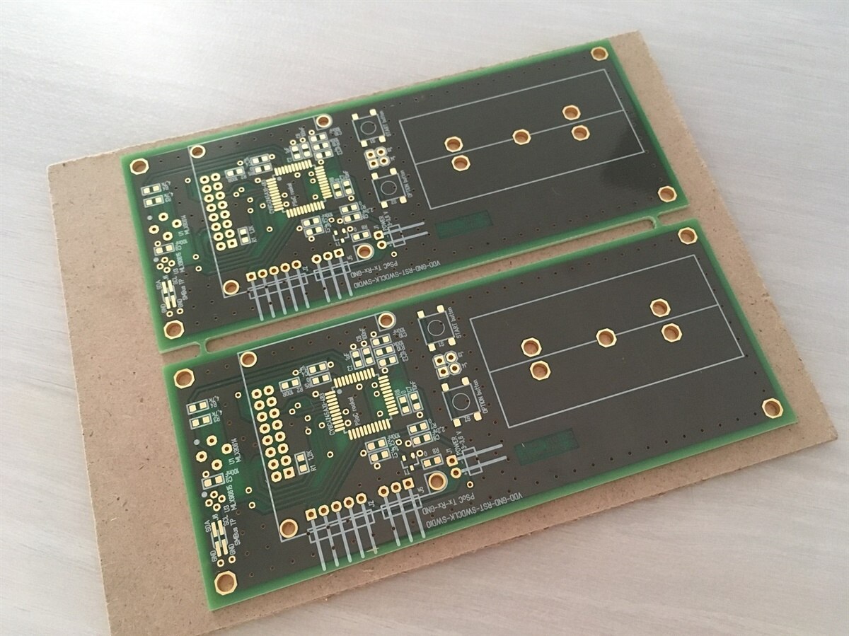
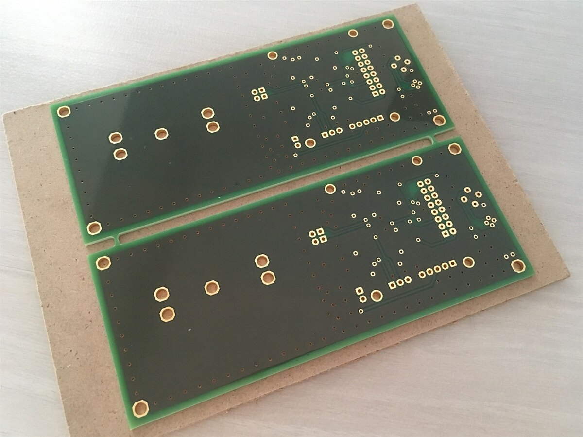
 

PCB

After a week, the PCBs were ready. Quite different than the first one, don't you think?

image

image

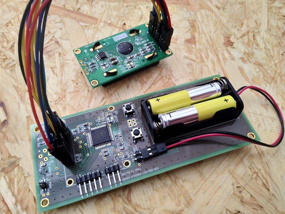
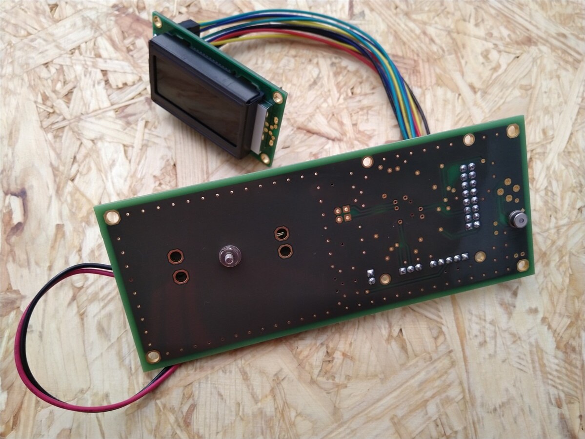
This is what the thermometer looks like after the assembly:

image

image


Demonstration video

What currently works is only the ambient temperature measurement (second line of the 8x2 character LCD). That is why I added the Sensirion thermometer for comparison.

The object temperature (first line of the LCD) is OK, but the emissivity is set to a not meaningful value of 0,09. Changing the emissivity doesn't work yet. The API is finished, however, I am struggling with the button control functions (described below).


You don't have permission to edit metadata of this video.
Edit media
x
image
Upload Preview
image


Design files

I put everything into a shared Google Drive folder. IRthermometer v2.T3001 is a schematics and PCB file. PSoC project will be added after I get the project into a better working state. (Meantime it is possible to explore the older revision project.)


What went wrong

  • I chose an impossible to obtain LCD. There are two types of LCD in the 8x2 characters format. They either have a connector above the LCD, or on the side. I had the first type lying in my component box, so I decided to use it. However, this type doesn't have the charge pump (I need to use a 3,3 V version) if you want to buy the LCD from official distributors. My LCD was some garbage bought from China on eBay. I have to buy a different LCD in the other format and use wires instead of a connector.
  • Second, I used a component symbol and footprint in the CAD program drawn by some user. Even if I got the LCD in the format I needed, the mounting holes were shifted a few millimeters, so I could mount the LCD in 1 or 2 stands of 4. All the LCDs have exactly the same format, so the person that drew it didn't bother to try it or delete it after finding out that is doesn't fit. Next time, I will draw the components myself, as almost all engineers do.


Help needed

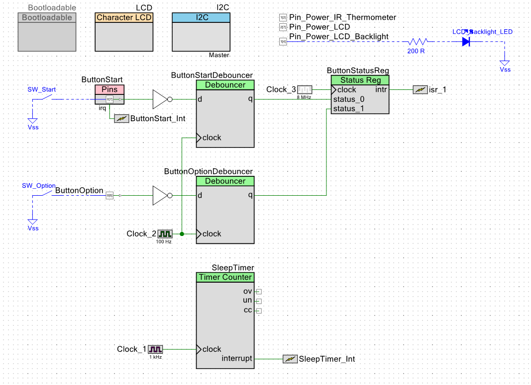
  • I am currently stuck and not sure, how to deal with the button controls. Here is the current situation: the buttons are not debounced in HW. Also, an interrupt is needed to wake up from the stop mode. In addition to that, I use button interrupt to for waking from the 5 seconds sleep mode before entering the stop mode. More about the firmware state machine is here: "No lies" IR Thermometer - part III , the diagram makes it pretty clear (I believe).
  • PSoC offers a Debounce button component, but of course the interrupt input cannot be debounced. It doesn't matter for "wake up from stop mode", but it does in waking up from the "wake up from 5 second sleep" mode.
  • Should the buttons react to the button press, or perform something after the button release? Is it a good idea to use the button interrupt at all? Maybe I could set a periodic timer and debounce the buttons every time the code enters the interrupt (I don't mean waiting to debounce, but just checking how much time passed since the last interrupt or something similar).
  • I mixed functionality that needs interrupts and debounced buttons and just struggle to get away. The rest of the functionality (emissivity changing etc. is ready and working).


Here is one variant of my work in progress PSoC ideas:

image


Thank you for reading. Any help is appreciated.


David

  • Sign in to reply

Top Comments

  • shabaz
    shabaz over 6 years ago +4
    Hi David, This is a stunning looking project! Great demo video too. I too came across the same problem as you, that some LCDs are missing the charge pump (they need the IC and a few caps soldered, if they…
  • 14rhb
    14rhb over 6 years ago +2
    Hi David, This is a very professional build and great write up - well done. I'm not sure if you could implement this, but on microcontrollers I sometimes generate a small interrupt ticker that can be used…
  • koudelad
    koudelad over 6 years ago +2
    Thank you, 14rhb and shabaz for the kind words and ideas. I will try to implement the algorithm you suggest, as it will be more "portable" in case of changing the microcontroller family in the future.…
  • Marvian
    Marvian over 1 year ago

    Hi David, I have same project and I could not communicate with MLX90614. I appreciate if you share your PSOC code so I can figure out it.

    Thanks,

    Marvian

    • Cancel
    • Vote Up 0 Vote Down
    • Sign in to reply
    • More
    • Cancel
  • koudelad
    koudelad over 6 years ago

    Thank you for the parts list and suggestions. I might try one of those in the future.


    I also thought the Sharp memory display could be a great display for similar devices: https://www.adafruit.com/product/1393 . The only disadvantage is a lack of back light.

    However, I still have respect from the graphic displays. The alphanumeric displays are quite easy to use.

    • Cancel
    • Vote Up 0 Vote Down
    • Sign in to reply
    • More
    • Cancel
  • shabaz
    shabaz over 6 years ago in reply to koudelad

    Hi David,


    If the tracks look anything like this topology (this is the more expensive one which came with the parts fitted),

    image

    then I believe the parts needed are:

    TC7660 Switched Cap Voltage Converter ICTC7660 Switched Cap Voltage Converter IC

    2 x 10u Tant Capacitor10u Tant Capacitor

    0R 0805 Resistor0R 0805 Resistor


    I did buy these parts for the couple of LCD screens I had since I didn't want to waste them, but I have not tried it yet.

    Like you am unlikely to buy these again, since I'm not sure the fix will even work, and too much effort to then troubleshoot if it doesn't!

    • Cancel
    • Vote Up +1 Vote Down
    • Sign in to reply
    • More
    • Cancel
  • mcb1
    mcb1 over 6 years ago in reply to koudelad

    I semi discovered the 3v3 versions when I received one in an order from Terry King (www.yourduino).

    He was puzzled as he never stocked them, but somehow one slipped through from the supplier.


    Looks like you have a supplier close at reasonable prices.

    16x2 LCD Display Yellow/Green LED Backlight 3.3V | LCD16X2BL3V3 |

    Basic 16x2 Character LCD - White on Black 3.3V | LCD-09052 | SparkFun


    Sparkfun listed prices are quite high, but they have this very universal communications version with an onboard ATmega328

    https://www.sparkfun.com/products/14072


    Mark

    • Cancel
    • Vote Up +2 Vote Down
    • Sign in to reply
    • More
    • Cancel
  • koudelad
    koudelad over 6 years ago in reply to mcb1

    Hello,

    I actually considered this option, too. I bought about 4 LCD types from eBay and noticed they have an unpopulated IC. The logic is OK with just 3 V, but for contrast, at least additional -1,5 V is needed. The datasheets don't mention this circuit in detail. I even quoted some distributors and manufacturers, without success. I mean I literally asked for the same LCD version, just with the charge pump assembled. One manufactured told me they would need to adjust the PCB and whether I am willing to buy 1k of the LCDs. The rest didn't answer or declined.


    Finally I found just one model from Raystar, but with the other "LCD vs connector" layout. I will buy them and just wire them manually, not connect them via the 2,54 mm  (0,1') header.


    I didn't want to reverse engineer the LCD that much. I know it is just an 8-pin IC and a few capacitors, but I didn't want to spend time doing it. My takeway is to do all the future BOMs using components from major distributors and forget eBay. The quality of those components is bad, anyway.


    David

    • Cancel
    • Vote Up +2 Vote Down
    • Sign in to reply
    • More
    • Cancel
>
element14 Community

element14 is the first online community specifically for engineers. Connect with your peers and get expert answers to your questions.

  • Members
  • Learn
  • Technologies
  • Challenges & Projects
  • Products
  • Store
  • About Us
  • Feedback & Support
  • FAQs
  • Terms of Use
  • Privacy Policy
  • Legal and Copyright Notices
  • Sitemap
  • Cookies

An Avnet Company © 2025 Premier Farnell Limited. All Rights Reserved.

Premier Farnell Ltd, registered in England and Wales (no 00876412), registered office: Farnell House, Forge Lane, Leeds LS12 2NE.

ICP 备案号 10220084.

Follow element14

  • X
  • Facebook
  • linkedin
  • YouTube