element14 Community
element14 Community
    Register Log In
  • Site
  • Search
  • Log In Register
  • About Us
  • Community Hub
    Community Hub
    • What's New on element14
    • Feedback and Support
    • Benefits of Membership
    • Personal Blogs
    • Members Area
    • Achievement Levels
  • Learn
    Learn
    • Ask an Expert
    • eBooks
    • element14 presents
    • Learning Center
    • Tech Spotlight
    • STEM Academy
    • Webinars, Training and Events
    • Learning Groups
  • Technologies
    Technologies
    • 3D Printing
    • FPGA
    • Industrial Automation
    • Internet of Things
    • Power & Energy
    • Sensors
    • Technology Groups
  • Challenges & Projects
    Challenges & Projects
    • Design Challenges
    • element14 presents Projects
    • Project14
    • Arduino Projects
    • Raspberry Pi Projects
    • Project Groups
  • Products
    Products
    • Arduino
    • Avnet Boards Community
    • Dev Tools
    • Manufacturers
    • Multicomp Pro
    • Product Groups
    • Raspberry Pi
    • RoadTests & Reviews
  • Store
    Store
    • Visit Your Store
    • Choose another store...
      • Europe
      •  Austria (German)
      •  Belgium (Dutch, French)
      •  Bulgaria (Bulgarian)
      •  Czech Republic (Czech)
      •  Denmark (Danish)
      •  Estonia (Estonian)
      •  Finland (Finnish)
      •  France (French)
      •  Germany (German)
      •  Hungary (Hungarian)
      •  Ireland
      •  Israel
      •  Italy (Italian)
      •  Latvia (Latvian)
      •  
      •  Lithuania (Lithuanian)
      •  Netherlands (Dutch)
      •  Norway (Norwegian)
      •  Poland (Polish)
      •  Portugal (Portuguese)
      •  Romania (Romanian)
      •  Russia (Russian)
      •  Slovakia (Slovak)
      •  Slovenia (Slovenian)
      •  Spain (Spanish)
      •  Sweden (Swedish)
      •  Switzerland(German, French)
      •  Turkey (Turkish)
      •  United Kingdom
      • Asia Pacific
      •  Australia
      •  China
      •  Hong Kong
      •  India
      •  Korea (Korean)
      •  Malaysia
      •  New Zealand
      •  Philippines
      •  Singapore
      •  Taiwan
      •  Thailand (Thai)
      • Americas
      •  Brazil (Portuguese)
      •  Canada
      •  Mexico (Spanish)
      •  United States
      Can't find the country/region you're looking for? Visit our export site or find a local distributor.
  • Translate
  • Profile
  • Settings
Test Instrumentation
  • Challenges & Projects
  • Project14
  • Test Instrumentation
  • More
  • Cancel
Test Instrumentation
Blog Project PITS update
  • Blog
  • Forum
  • Documents
  • Events
  • Polls
  • Files
  • Members
  • Mentions
  • Sub-Groups
  • Tags
  • More
  • Cancel
  • New
Join Test Instrumentation to participate - click to join for free!
  • Share
  • More
  • Cancel
Group Actions
  • Group RSS
  • More
  • Cancel
Engagement
  • Author Author: three-phase
  • Date Created: 2 Dec 2018 10:12 PM Date Created
  • Views 2048 views
  • Likes 8 likes
  • Comments 10 comments
  • mcgg relay
  • photodiode
  • current pickup
  • comparator
  • scits
  • diytestinstruch
Related
Recommended

Project PITS update

three-phase
three-phase
2 Dec 2018
image

Test Instrumentation

Enter Your Electronics & Design Project for a chance to win a Grand Prize for Originality, a Tool Set, and a $100 Shopping Cart!

Back to The Project14 homepage image

Project14 Home
Monthly Themes
Monthly Theme Poll


Project PITS has moved forward since the initial prototype was seen to work.


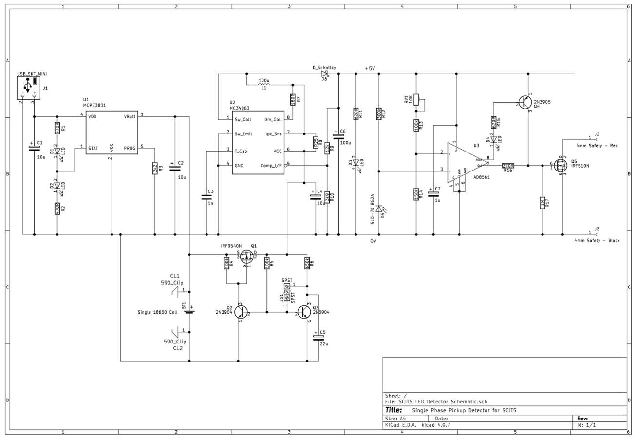
Since deciding that the best place for the on / off switch was between the charger and the boost circuit, the pre-manufactured board could not be utilised. The circuit has therefore been expanded utilising a MCP73831 charger integrated circuit from Microchip and a MC34063 for On Semiconductors to build up the boost circuit to convert the 3.7V from the 18650 cell to the required 5V.


image


image

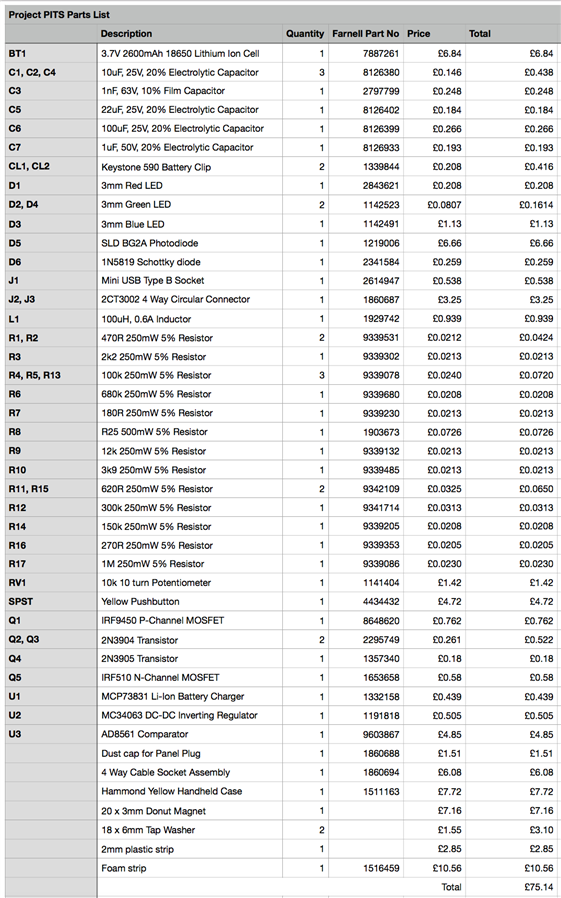
This has created a much larger parts list as seen above, now giving a total parts cost of just over £75.00. The only major part missing from the cost now will be the cost of the PCB. Given the increase in components, the PCB has substantially changed but I have still managed to keep it within the case size.


Front Copper Layout

image

Rear Copper Layout

image

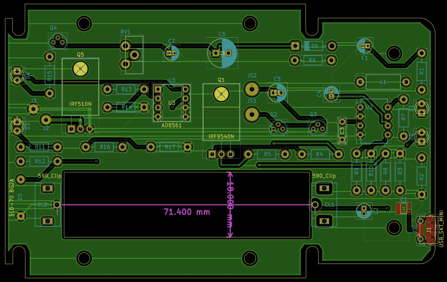
At the front, the board has been shortened to give room for the push button and 4 way socket that will be used to make connections to both the photodiode and the injection test set.


I am wondering If I should have a complete cutout of the copper around the whole of the battery positive clip as appose to just around the solder pads.


The battery clips themselves  have been positioned on the PCB utilising measurements from a manufactured battery holder, to get the correct tension on the spring clips. A couple of concerns are surrounding the connections to the USB socket and whether or not a copper track should be run up to the negative battery clip from this. I am also wondering if I should look at fusing  from the positive battery clip to the outgoing circuit and incoming from the charger. I am just wary of the power capability within the lithium ion cells and looking to prevent potential issues in the event of faults occurring.


image


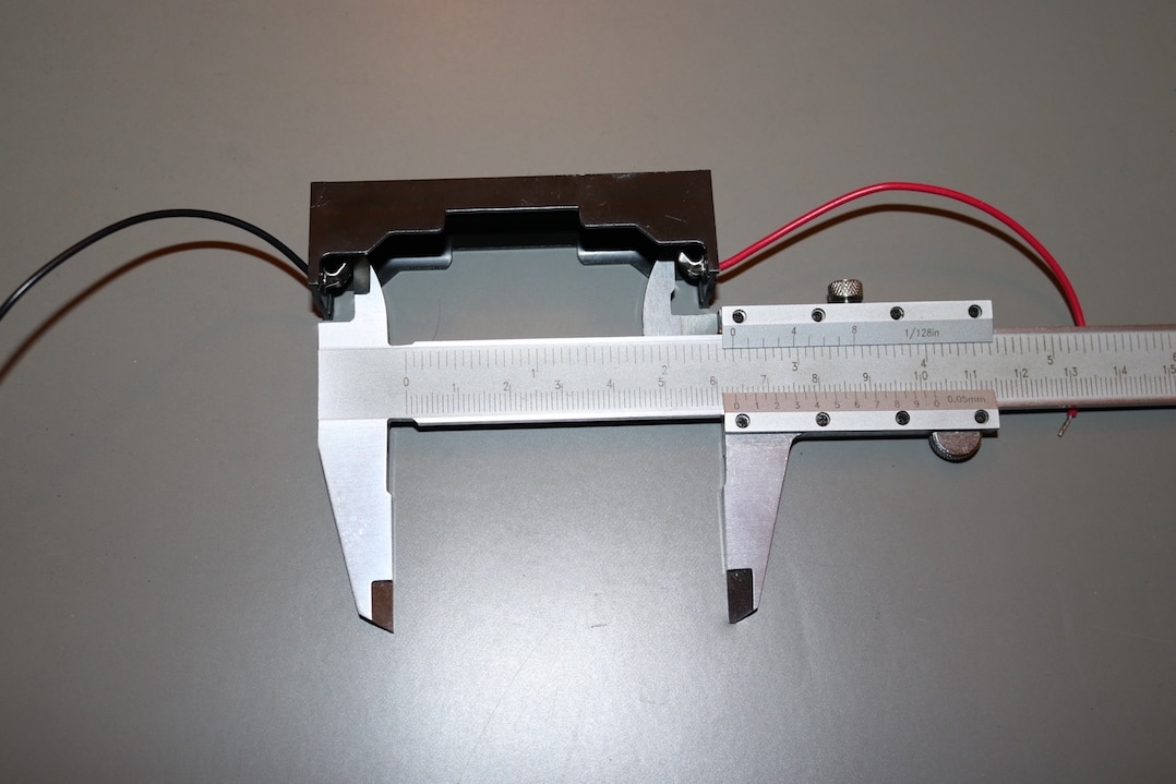
Practically, not much has moved on. The 4 way connector and on / off switch have been mounted into the front of the case. I will need to drill holes for the LEDs and cut out for the USB connector, but this will not be done until I have a PCB to confirm the positioning.


imageimage

The next thing to do will be to order the required parts in and select someone to manufacture the PCB and ensure that I can generate the correct information that they require.

  • Sign in to reply

Top Comments

  • three-phase
    three-phase over 6 years ago +4
    I have now added a single 1A poly fuse to the battery positive connection. This pretty much completes the initial circuit. Over the weekend, I hope to set up the soft latch circuit and try it with the…
  • three-phase
    three-phase over 6 years ago in reply to three-phase +3
    Found the problem for the keep out area, The 'no copper pour' option is deselected by default, so selecting that removed the copper from the area.
  • genebren
    genebren over 6 years ago +3
    Donald, The updates to your project look great. The MCP73831 is a great choice for the Li Ion charging circuit. On the boost side, you could greatly simplify your circuit by using a boost convertor with…
Parents
  • shabaz
    shabaz over 6 years ago

    Hi Donald,


    Nice-looking design!

    Regarding the clips, I've used the ones that you've specified, and with hindsight I'd definitely remove all ground plane on the top surface, in the U-shape that the clip occupies.. something like this basically:

    image

    The yellow area would be the minimum area where there should be no ground plane I think. Otherwise, the metal clip is only separated by thin solder resist, because it sits very flush on the PCB.

    As you say, it could also be good to have some extra protection. A nice bit of protection would be a polyfuse, they are super-cheap.

    Even without that, it can be handy to have space for a series resistor, that could be useful for desoldering to make current measurements during development for instance, and in normal use is a zero-ohm resistor.

    But if you use a polyfuse, you don't need space for an additional zero-ohm resistor; the polyfuse can be desoldered for the current measurement.


    EDIT: Now I think about it, an even better way would be to have a small U-shaped copper area on top, which is then separated by an air gap to the ground plane. That way, when the clip is soldered down, the solder from the underside of the board can fill up the via too. But, this is overkill, because the metal connector is actually very high quality, and doesn't have much force applied in a direction that would cause it to weaken the joint, because it sits very tightly square against the PCB. Plus, if it really was a concern, epoxy glue could be used.

    • Cancel
    • Vote Up +2 Vote Down
    • Sign in to reply
    • More
    • Cancel
  • three-phase
    three-phase over 6 years ago in reply to shabaz

    Many thanks shabaz for the advice.


    I have found some polyfusas on Farnell that should be adequate, so will look to add those in. I will either need to redesign the track layouts to keep it as a single fuse, or use two. One for the charger circuit and then a separate one to the booster circuit.


    Adding the cut out around the battery clip is going to take some more research. I added a keep out area but the front copper still covers the area. I tried your second approach to create a u-shaped copper area, but it will not allow me to join the pads of the battery clip together with a track.


    image


    Must rename the battery clips to positive and negative as well.


    Kind regards.

    • Cancel
    • Vote Up +2 Vote Down
    • Sign in to reply
    • More
    • Cancel
Comment
  • three-phase
    three-phase over 6 years ago in reply to shabaz

    Many thanks shabaz for the advice.


    I have found some polyfusas on Farnell that should be adequate, so will look to add those in. I will either need to redesign the track layouts to keep it as a single fuse, or use two. One for the charger circuit and then a separate one to the booster circuit.


    Adding the cut out around the battery clip is going to take some more research. I added a keep out area but the front copper still covers the area. I tried your second approach to create a u-shaped copper area, but it will not allow me to join the pads of the battery clip together with a track.


    image


    Must rename the battery clips to positive and negative as well.


    Kind regards.

    • Cancel
    • Vote Up +2 Vote Down
    • Sign in to reply
    • More
    • Cancel
Children
  • three-phase
    three-phase over 6 years ago in reply to three-phase

    Found the problem for the keep out area,


    image


    The 'no copper pour' option is deselected by default, so selecting that removed the copper from the area.


    image


    image

    • Cancel
    • Vote Up +3 Vote Down
    • Sign in to reply
    • More
    • Cancel
element14 Community

element14 is the first online community specifically for engineers. Connect with your peers and get expert answers to your questions.

  • Members
  • Learn
  • Technologies
  • Challenges & Projects
  • Products
  • Store
  • About Us
  • Feedback & Support
  • FAQs
  • Terms of Use
  • Privacy Policy
  • Legal and Copyright Notices
  • Sitemap
  • Cookies

An Avnet Company © 2025 Premier Farnell Limited. All Rights Reserved.

Premier Farnell Ltd, registered in England and Wales (no 00876412), registered office: Farnell House, Forge Lane, Leeds LS12 2NE.

ICP 备案号 10220084.

Follow element14

  • X
  • Facebook
  • linkedin
  • YouTube