element14 Community
element14 Community
    Register Log In
  • Site
  • Search
  • Log In Register
  • Community Hub
    Community Hub
    • What's New on element14
    • Feedback and Support
    • Benefits of Membership
    • Personal Blogs
    • Members Area
    • Achievement Levels
  • Learn
    Learn
    • Ask an Expert
    • eBooks
    • element14 presents
    • Learning Center
    • Tech Spotlight
    • STEM Academy
    • Webinars, Training and Events
    • Learning Groups
  • Technologies
    Technologies
    • 3D Printing
    • FPGA
    • Industrial Automation
    • Internet of Things
    • Power & Energy
    • Sensors
    • Technology Groups
  • Challenges & Projects
    Challenges & Projects
    • Design Challenges
    • element14 presents Projects
    • Project14
    • Arduino Projects
    • Raspberry Pi Projects
    • Project Groups
  • Products
    Products
    • Arduino
    • Avnet Boards Community
    • Dev Tools
    • Manufacturers
    • Multicomp Pro
    • Product Groups
    • Raspberry Pi
    • RoadTests & Reviews
  • Store
    Store
    • Visit Your Store
    • Choose another store...
      • Europe
      •  Austria (German)
      •  Belgium (Dutch, French)
      •  Bulgaria (Bulgarian)
      •  Czech Republic (Czech)
      •  Denmark (Danish)
      •  Estonia (Estonian)
      •  Finland (Finnish)
      •  France (French)
      •  Germany (German)
      •  Hungary (Hungarian)
      •  Ireland
      •  Israel
      •  Italy (Italian)
      •  Latvia (Latvian)
      •  
      •  Lithuania (Lithuanian)
      •  Netherlands (Dutch)
      •  Norway (Norwegian)
      •  Poland (Polish)
      •  Portugal (Portuguese)
      •  Romania (Romanian)
      •  Russia (Russian)
      •  Slovakia (Slovak)
      •  Slovenia (Slovenian)
      •  Spain (Spanish)
      •  Sweden (Swedish)
      •  Switzerland(German, French)
      •  Turkey (Turkish)
      •  United Kingdom
      • Asia Pacific
      •  Australia
      •  China
      •  Hong Kong
      •  India
      •  Korea (Korean)
      •  Malaysia
      •  New Zealand
      •  Philippines
      •  Singapore
      •  Taiwan
      •  Thailand (Thai)
      • Americas
      •  Brazil (Portuguese)
      •  Canada
      •  Mexico (Spanish)
      •  United States
      Can't find the country/region you're looking for? Visit our export site or find a local distributor.
  • Translate
  • Profile
  • Settings
The Holiday Special
  • Challenges & Projects
  • Project14
  • The Holiday Special
  • More
  • Cancel
The Holiday Special
Blog Desktop Christmas Tree
  • Blog
  • Forum
  • Documents
  • Events
  • Polls
  • Files
  • Members
  • Mentions
  • Sub-Groups
  • Tags
  • More
  • Cancel
  • New
Join The Holiday Special to participate - click to join for free!
  • Share
  • More
  • Cancel
Group Actions
  • Group RSS
  • More
  • Cancel
Engagement
  • Author Author: jofas
  • Date Created: 9 Jan 2018 3:43 PM Date Created
  • Views 2654 views
  • Likes 14 likes
  • Comments 7 comments
  • merryboxesledsch
  • holiday projects
  • holidayspecial19ch
  • led
  • rgb
  • holidayspecialch
Related
Recommended

Desktop Christmas Tree

jofas
jofas
9 Jan 2018
image

The Holiday Special

Enter Your Project for a chance to win $100 Shopping Carts, Gifts to Give, and a 3D Printer Prize!

Back to The Project14 homepage image

Project14 Home
Monthly Themes
Monthly Theme Poll


Introduction

Happy Holidays!

My project is a small plastic Christmas tree that can sit on your desk to bring holiday cheer to your workspace. The lights have a "twinkle" effect to make your holidays even more magical.


Here's a quick overview of this device:

  • Powered by a 12v wall-wart
  • 3D printed parts (had to use Shapeways for 3D printing since I don't have my own printer)
  • Custom made PCB
  • 24 LEDs of different colors
  • Uses an ATTiny24 to create the lighting effects
  • About 13cm tall, 11cm wide (at widest part)


Scroll down to the very bottom to see the demo video. Keep reading if you are interested in how I made this.


The Enclosure

For this project, I used FreeCAD to design the enclosure. The tree is made of four plastic pieces. The top part (the main tree shape) was designed as two halves. You can see that there are slots and tabs; this was my method of attaching all the pieces together (with some glue as well).

image

The base of the enclosure is a simple box to house the PCB. It has four tabs which allow it to attach to the slots in the pieces shown above. The base also has a removable piece which makes it easier to assemble the wiring and troubleshoot the circuit if there are any problems. Here is what the base looks like:

image

I uploaded these designs to Shapeways to get them printed. I don't have much experience with 3D design so I was really hoping there would be no problems. Unfortunately, when I received the pieces, I noticed there were two problems. First, I made the tabs the same size as the slots - they wouldn't fit. The tabs should have been slightly smaller than the slots. I ended up filing the tabs down until they could fit inside the slots. Second, the square base should have lined up with the square opening in the main tree part. Unfortunately, the base was about 2mm larger than the opening, so it wouldn't fit. To fix this, I cut the tabs off the base and just used plastic welder (two-component adhesive) to attach the base to the main tree part.


Aside from these fixes, I had to make one more modification to the parts (this time it was intentional). I drilled some holes in the tree pieces to stick LEDs through. I decided this would be easier than trying to design the part with holes in it already. I also had to drill a small hole into the base to allow the power cord through. Below you can see the two halves of the tree, one with holes drilled and the other without.

image


The Electronics

I used KiCad to design the electronics. Overall, the circuit works like this: there are 4 LEDs in series (each a different color), this makes a "strand". There are 6 of these strands total, three of them are always on and the other three are controlled (via three transistors) by the ATTiny using PWM to create a twinkling effect. There is also a voltage regulator (LM317T) to step down the 12v input to 5v for the ATTiny. Here is the original schematic. You may need to click on the image to see the full-size version.

image

Once I was satisfied with the schematic, I designed the PCB. It is a two-sided PCB, but there are no components on the backside. The top is the ground plane, the bottom is the 12v plane. The image below shows the top copper on the left (red) and the bottom copper on the right (green).

image

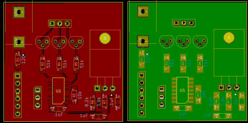
I sent this design to OSH Park and received three boards a couple weeks later. Since this was my first PCB design, I was quite happy with the results. There were only two problems. First, the footprint of the barrel jack did not match the actual component I had. I ended up abandoning the barrel jack and just soldered the power wires directly to the board. This actually made the assembly process easier, so I wasn't upset about it. Secondly, some of the resistor values were wrong in the schematic (particularly the 51k transistor base resistors). I'm not sure why I used those values, my prototype breadboard circuit used 1k resistors. Fortunately, it is easy to just use different resistors. I should also note that you may notice other resistor values are different than the schematic. This is because I did not have that particular value available in SMD form, so I had to use a resistor that was close enough. You can see the front/back of the blank board below.

After soldering the components onto the board, here is the result.image

image

The Code

Before soldering the ATTiny24 to the PCB, I programmed it to use PWM to change the brightness of the LEDs in a specific pattern. The three PWM strands each change brightness individually and at different times. I wrote the code in notepad++ and uploaded it with a programmer. This was the first time I have programmed an AVR without the Arduino IDE. This was a very frustrating experience, but I learned a lot and it was definitely worth the pain in the end. For some reason I am having trouble embedding the code into this post, but you can see it on pastebin here.


The Assembly

Now that the microcontroller was programmed, everything was soldered to the board, and all holes were drilled into the plastic pieces, I was ready to begin assembly. It was tedious, but I connected the LEDs with short wires and pushed them through the holes in the plastic. The drilled holes were small enough that the LEDs fit snug without needing any glue. Once I had the LEDs in place, I tested them before attaching the base of the tree. You can see the successful test below.

Lastly, I used plastic welder to attach the base. Here's what that looks like:image

image


Conclusion

Here's a quick video showing the final product in action.

You don't have permission to edit metadata of this video.
Edit media
x
image
Upload Preview
image


Overall, this was a great project for me. I learned a lot about PCB design, 3D design, and programming AVR microcontrollers. In the future, I think I will try to remake this again but use all RGB LEDs and add wifi control - I imagine controlling the colors of the LEDs with my phone over wifi.

  • Sign in to reply

Top Comments

  • mcb1
    mcb1 over 7 years ago +2
    This is great. The use of the full 3D tree makes this better than the other 2D versions, and given the first time these little 'errors' are understandable, and you overcame them. You could probably drop…
  • ntewinkel
    ntewinkel over 7 years ago +2
    Great project, Joey! > Unfortunately, I had to use Shapeways to print this version and it was expensive! I've been thinking of using some 3D printing service myself, for an upcoming project, but agree…
  • genebren
    genebren over 7 years ago +1
    Joey, Very nice! What a great project and a great way for you to learn and/or expand on your skills. I look forward to see your next revision. Gene
  • dubbie
    dubbie over 5 years ago

    A great project. I liked the 3D printed Christmas trees - I am inspired to have a think about doing the same. I use TinkerCAD which is not the best for curved surfaces, but I might be able to make something. Also, a very neat PCB. Impressive for a first design.


    Dubbie

    • Cancel
    • Vote Up 0 Vote Down
    • Sign in to reply
    • More
    • Cancel
  • abrain
    abrain over 5 years ago

    Very nice project, and a great first PCB, nicely done! Lovely tidy soldering too! image

    The 3D printed tree was a very nice touch, it looks really good, much better than a 2D one - a great inspirational example of what can be achieved, well done!


    A

    • Cancel
    • Vote Up +1 Vote Down
    • Sign in to reply
    • More
    • Cancel
  • ntewinkel
    ntewinkel over 7 years ago

    Great project, Joey!

    >Unfortunately, I had to use Shapeways to print this version and it was expensive!


    I've been thinking of using some 3D printing service myself, for an upcoming project, but agree that price and turnaround time can be a problem.

    Would a crowd-based service like 3dhubs or MakeXYZ be a bit more budget friendly? https://www.3dhubs.com/   https://www.makexyz.com/

    (I think there are even some printers in my local area, and I live in a small townish kind of place)


    Cheers,

    -Nico

    • Cancel
    • Vote Up +2 Vote Down
    • Sign in to reply
    • More
    • Cancel
  • mcb1
    mcb1 over 7 years ago in reply to jofas

    jofas


    Erik developed them as a kickstarter and has progressed to the Pro version.

    There are a few limitations with the orginal Digispark, but you should be able to get away with what you're doing just fine.

    I had thought there was a 3 mosfet shield, but it looks like the protoboard might be the easiest ... or adding it onto a mosfet drver board.


    For your wireless solutions you might want to look at the ESP8266 or the newer ESP32.

    ESP32 and Mongoose OS - Intro

    ESP32 and Mongoose OS - First Application

    ESP32 and Mongoose OS - Issues

    I'm still coming to grips with it, but apparently you can program them in the Arduino IDE as well (like the Digisparks)


    Mark

    • Cancel
    • Vote Up +1 Vote Down
    • Sign in to reply
    • More
    • Cancel
  • jofas
    jofas over 7 years ago in reply to mcb1

    Interesting, I didn't know about those. Thanks for the tip!

    • Cancel
    • Vote Up 0 Vote Down
    • Sign in to reply
    • More
    • Cancel
>
element14 Community

element14 is the first online community specifically for engineers. Connect with your peers and get expert answers to your questions.

  • Members
  • Learn
  • Technologies
  • Challenges & Projects
  • Products
  • Store
  • About Us
  • Feedback & Support
  • FAQs
  • Terms of Use
  • Privacy Policy
  • Legal and Copyright Notices
  • Sitemap
  • Cookies

An Avnet Company © 2025 Premier Farnell Limited. All Rights Reserved.

Premier Farnell Ltd, registered in England and Wales (no 00876412), registered office: Farnell House, Forge Lane, Leeds LS12 2NE.

ICP 备案号 10220084.

Follow element14

  • X
  • Facebook
  • linkedin
  • YouTube