element14 Community
element14 Community
    Register Log In
  • Site
  • Search
  • Log In Register
  • Community Hub
    Community Hub
    • What's New on element14
    • Feedback and Support
    • Benefits of Membership
    • Personal Blogs
    • Members Area
    • Achievement Levels
  • Learn
    Learn
    • Ask an Expert
    • eBooks
    • element14 presents
    • Learning Center
    • Tech Spotlight
    • STEM Academy
    • Webinars, Training and Events
    • Learning Groups
  • Technologies
    Technologies
    • 3D Printing
    • FPGA
    • Industrial Automation
    • Internet of Things
    • Power & Energy
    • Sensors
    • Technology Groups
  • Challenges & Projects
    Challenges & Projects
    • Design Challenges
    • element14 presents Projects
    • Project14
    • Arduino Projects
    • Raspberry Pi Projects
    • Project Groups
  • Products
    Products
    • Arduino
    • Avnet & Tria Boards Community
    • Dev Tools
    • Manufacturers
    • Multicomp Pro
    • Product Groups
    • Raspberry Pi
    • RoadTests & Reviews
  • About Us
  • Store
    Store
    • Visit Your Store
    • Choose another store...
      • Europe
      •  Austria (German)
      •  Belgium (Dutch, French)
      •  Bulgaria (Bulgarian)
      •  Czech Republic (Czech)
      •  Denmark (Danish)
      •  Estonia (Estonian)
      •  Finland (Finnish)
      •  France (French)
      •  Germany (German)
      •  Hungary (Hungarian)
      •  Ireland
      •  Israel
      •  Italy (Italian)
      •  Latvia (Latvian)
      •  
      •  Lithuania (Lithuanian)
      •  Netherlands (Dutch)
      •  Norway (Norwegian)
      •  Poland (Polish)
      •  Portugal (Portuguese)
      •  Romania (Romanian)
      •  Russia (Russian)
      •  Slovakia (Slovak)
      •  Slovenia (Slovenian)
      •  Spain (Spanish)
      •  Sweden (Swedish)
      •  Switzerland(German, French)
      •  Turkey (Turkish)
      •  United Kingdom
      • Asia Pacific
      •  Australia
      •  China
      •  Hong Kong
      •  India
      •  Korea (Korean)
      •  Malaysia
      •  New Zealand
      •  Philippines
      •  Singapore
      •  Taiwan
      •  Thailand (Thai)
      • Americas
      •  Brazil (Portuguese)
      •  Canada
      •  Mexico (Spanish)
      •  United States
      Can't find the country/region you're looking for? Visit our export site or find a local distributor.
  • Translate
  • Profile
  • Settings
Learning Center
  • Learn
  • More
Learning Center
Blog 8Bit adder from discrete transistors
  • Blog
  • Documents
  • Polls
  • Members
  • Mentions
  • Sub-Groups
  • Tags
  • More
  • Cancel
  • New
Join Learning Center to participate - click to join for free!
  • Share
  • More
  • Cancel
Group Actions
  • Group RSS
  • More
  • Cancel
Engagement
  • Author Author: RobinTheMaker
  • Date Created: 14 Nov 2024 1:50 PM Date Created
  • Views 2975 views
  • Likes 12 likes
  • Comments 6 comments
  • logic gate project
  • ciruit design
  • transistor
  • logic gates
  • pcb
  • adder
Related
Recommended

8Bit adder from discrete transistors

RobinTheMaker
RobinTheMaker
14 Nov 2024
In this project I tried to build the simplest calculater possible from discrete transistors in order to learn more about digital logic on the most basic level.

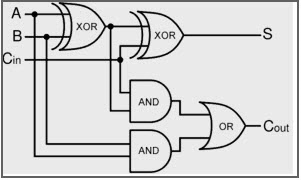
 started experimenting with single transistors on bread boards, building simple logic gates. The next step was to assemble the logic gates into a full adder. At first I used multiple different types of logic gates like in the following image.

image

I made the circuit on a breadboard and even build a second one to hook together. They worked as expected although the leds on the output were quite dim. But I didn't let that stop me and pushed trough with creating a PCB and ordered it. After hours of assembling half the board with 72 out of 144 transistors and twice as many resistors, I plugged it in only to see that the adders worked on their own but the carry out voltage was to low to turn on the next transistor. 

I created a simulation of the circuit with CircuitJS which showed me, that with my current architecture there are some cases where the voltage drop across the transistors is to great to turn on the next transistor. 

After some research I found an alternate design that only uses NOR gates that are very simple to implement with a single transistor and three resistors per gate. This effectivly cut the total number of transistors in half and made the design actually work. This time I tested everything in with simulations before ordering and assembling a PCB.

imageimage

I got the PCBs and was very exited because I had never ordered ones with ENIG imersion gold finish and together with the purple it just looks amazing. This is a show piece after all and I am planning on building a nice wooden enclousure for it. 
I started the assembly progress by first soldering the USB C with some solder paste and a hot air gun and then continued on to the first full adder. After soldering 9 transistors and over 30 resistors I had enough components on the board to test basic functionality. But after flicking the switches in all possible combinations all the output led's stayed dim and unlit and the panic started creeping in.
After a quick probing session with the multimeter I turned to the schematic and board layout in KiCad to reference some things. I found the coulprit quite fast. I don't know how it happend or how I never noticed it but at some point I messed up the connection between footprint and schematic. The pin numbers didn't mach up correctly. In the schematic the base of the transistor is pin number 1. On the physical part of the BC547b transistor the base is the middle leg but on the footprint the pins are numbered from left to right making the the base the left most pin.So after a short rage I came back to my senses and researched if there is a npn transistor with similar characteristics to the BC547b but the weird pin out I accidentally created. The only one I could find that might fit is the SC945 but I have to rotate it 180 degrees to make it align with the correct pins. 
I will post another update once I receive the new parts. Until then remember to double check your footprints even if they seem very simple.

GitHub

  • Sign in to reply

Top Comments

  • DAB
    DAB 11 months ago +1
    One of my first purchases from the surplus market was an old RTL board from some computer, back in the 1960's. So your going back to that era for a project brought a smile to my face as I remembered…
  • Stuart_S
    Stuart_S 7 days ago +1
    We did this circuit in one of our digital practicals at Uni a while back (that was converted to VHDL) , build a half adder and full adder (half adder with carry). Our add with carry features two XOR, two…
  • Stuart_S
    Stuart_S 7 days ago

    We did this circuit  in one of our digital practicals at Uni a while back (that was converted to VHDL), build a half adder and full adder (half adder with carry). Our add with carry features two XOR, two ANDs and an OR -which appears as one of your bit adding modules. Maybe there's an exercise here using De-Morgan's theorem to reduce the chip count.  image

                                  Half Adder

    image

                         Full Adder

    I've included the truth tables and simulations for reference and support

    • Cancel
    • Vote Up +1 Vote Down
    • Sign in to reply
    • More
    • Cancel
  • DAB
    DAB 11 months ago

    One of my first purchases from the surplus market was an old RTL board from some computer, back in the 1960's.

    So your going back to that era for a project brought a smile to my face as I remembered the fun I had tracing the circuit from the logic boards.

    • Cancel
    • Vote Up +1 Vote Down
    • Sign in to reply
    • More
    • Cancel
  • RobinTheMaker
    RobinTheMaker 11 months ago in reply to michaelkellett

    No worries. I appreciate you wanting to help. Thanks Thumbsup

    • Cancel
    • Vote Up 0 Vote Down
    • Sign in to reply
    • More
    • Cancel
  • michaelkellett
    michaelkellett 11 months ago in reply to RobinTheMaker

    I looked at the https://electronics.stackexchange.com/questions/265567/building-a-full-adder-with-npn-bjt-transistors

    link but missed the bit where you said you had actually done it with NOR gates !

    Flushed

    MK

    • Cancel
    • Vote Up 0 Vote Down
    • Sign in to reply
    • More
    • Cancel
  • RobinTheMaker
    RobinTheMaker 11 months ago in reply to michaelkellett

    Thanks for your reply.

    As I wrote in my post I did end up using NOR gates build with one NPN and three resistors and I used the following schematic for each of the full adders:
    image

    Credit: jonk

    It does actually use half the transistors compared to my first design but that one wasn't optimized at all. 

    Yes you can squeeze in the TO92 in many funny ways but you definitly don't want to do that 72 times and the resulting pcb would look anything but nice.

    • Cancel
    • Vote Up 0 Vote Down
    • Sign in to reply
    • More
    • Cancel
>
element14 Community

element14 is the first online community specifically for engineers. Connect with your peers and get expert answers to your questions.

  • Members
  • Learn
  • Technologies
  • Challenges & Projects
  • Products
  • Store
  • About Us
  • Feedback & Support
  • FAQs
  • Terms of Use
  • Privacy Policy
  • Legal and Copyright Notices
  • Sitemap
  • Cookies

An Avnet Company © 2025 Premier Farnell Limited. All Rights Reserved.

Premier Farnell Ltd, registered in England and Wales (no 00876412), registered office: Farnell House, Forge Lane, Leeds LS12 2NE.

ICP 备案号 10220084.

Follow element14

  • X
  • Facebook
  • linkedin
  • YouTube