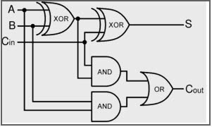
started experimenting with single transistors on bread boards, building simple logic gates. The next step was to assemble the logic gates into a full adder. At first I used multiple different types of logic gates like in the following image.

I made the circuit on a breadboard and even build a second one to hook together. They worked as expected although the leds on the output were quite dim. But I didn't let that stop me and pushed trough with creating a PCB and ordered it. After hours of assembling half the board with 72 out of 144 transistors and twice as many resistors, I plugged it in only to see that the adders worked on their own but the carry out voltage was to low to turn on the next transistor.
I created a simulation of the circuit with CircuitJS which showed me, that with my current architecture there are some cases where the voltage drop across the transistors is to great to turn on the next transistor.
After some research I found an alternate design that only uses NOR gates that are very simple to implement with a single transistor and three resistors per gate. This effectivly cut the total number of transistors in half and made the design actually work. This time I tested everything in with simulations before ordering and assembling a PCB.


I got the PCBs and was very exited because I had never ordered ones with ENIG imersion gold finish and together with the purple it just looks amazing. This is a show piece after all and I am planning on building a nice wooden enclousure for it.
I started the assembly progress by first soldering the USB C with some solder paste and a hot air gun and then continued on to the first full adder. After soldering 9 transistors and over 30 resistors I had enough components on the board to test basic functionality. But after flicking the switches in all possible combinations all the output led's stayed dim and unlit and the panic started creeping in.
After a quick probing session with the multimeter I turned to the schematic and board layout in KiCad to reference some things. I found the coulprit quite fast. I don't know how it happend or how I never noticed it but at some point I messed up the connection between footprint and schematic. The pin numbers didn't mach up correctly. In the schematic the base of the transistor is pin number 1. On the physical part of the BC547b transistor the base is the middle leg but on the footprint the pins are numbered from left to right making the the base the left most pin.So after a short rage I came back to my senses and researched if there is a npn transistor with similar characteristics to the BC547b but the weird pin out I accidentally created. The only one I could find that might fit is the SC945 but I have to rotate it 180 degrees to make it align with the correct pins.
I will post another update once I receive the new parts. Until then remember to double check your footprints even if they seem very simple.
GitHub

Top Comments
-

michaelkellett
-
Cancel
-
Vote Up
0
Vote Down
-
-
Sign in to reply
-
More
-
Cancel
-

RobinTheMaker
in reply to michaelkellett
-
Cancel
-
Vote Up
0
Vote Down
-
-
Sign in to reply
-
More
-
Cancel
-

michaelkellett
in reply to RobinTheMaker
-
Cancel
-
Vote Up
0
Vote Down
-
-
Sign in to reply
-
More
-
Cancel
-

RobinTheMaker
in reply to michaelkellett
-
Cancel
-
Vote Up
0
Vote Down
-
-
Sign in to reply
-
More
-
Cancel
Comment-

RobinTheMaker
in reply to michaelkellett
-
Cancel
-
Vote Up
0
Vote Down
-
-
Sign in to reply
-
More
-
Cancel
Children