

 Sensors Series - Part 09 - Industrial Sensing
As programmable logic controllers (PLCs) evolve, they are quickly becoming an integral component within Industry 4.0 smart factories. This is due to a need for faster, low power, and innovative solutions. The IO-Link standard was created in part to give the legacy sensors that were previously installed the capabilities of a smart sensor. IO-Link is a point-to-point communication link with standardized connectors, cables, and protocols. This article explains IO-Link smart sensor technology, analyzes IO-Link sensor design, and discusses its advantages over traditional systems.
Related Components | Test Your Knowledge 
sponsored by 
2. Objectives
Upon completion of this module, you will be able to:
- Understand what an IO-Link is and its components
- Describe the IO-Link data communication protocol and its pin configuration
- Discuss the benefits of using IO-Link in Industry 4.0 by comparing it with conventional sensors
- Explain how to design an IO-Link smart sensor
3. Basic Concepts
1. Traditional Sensors
Traditional sensors typically consist of a sensing element and a method for transmitting data to a controller. Figure 1 illustrates how traditional sensors frequently send data in a unidirectional, analog format. This type of data transmission requires additional operations, including additional digital-to-analog and analog-to-digital conversions, which can add noise, not to mention increasing the cost and footprint of the device. As shown in Figure 1, a traditional binary sensor indicates the status of a switch, either ON or OFF. An ON signal would be represented by a high (24V) signal, while an OFF signal would be represented by a low (0V) signal. In most cases, the data flow of traditional sensors is limited to one direction, from the sensor to the controller, as indicated in Figure 1.
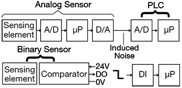
Figure 1: Traditional sensor block diagrams - Analog and Binary
Newer, more advanced sensors have replaced traditional sensors. The IO-Link standard was created to better meet the demands of Industry 4.0 where advanced smart sensors and reconfigurable factory floors will become commonplace. The following content offers a detailed explanation of the many benefits of IO-Link.
2. What is IO-Link?
IO-Link is a point-to-point, bus-independent, serial digital communication protocol defined by international standard IEC 61131-9. IO-Link is designed to link sensors and actuators to PLCs. IO-Link enables "last meter" digital data communication to sensors and actuators. It enables bidirectional transmission of parameterization and diagnostic data, where previously, only binary states (ON/OFF) or analog signals were communicated. A system with IO-Link functionality can benefit from reduced downtime for maintenance and increased flexibility when configuring and reconfiguring. IO-Link can transform a manual sensor installation into one which allows a user to "plug-and-play and walk away.”
3. The Components of IO-Link
Figure 2 depicts the block diagram of an IO-Link system, which is comprised of two types of components: the "IO-Link controller" and the "IO-Link device" (sensor or actuator). All IO-Link data exchange is controller-agent based, meaning the IO-Link controller communicates with IO-Link devices, collecting their data, and transmitting it to the higher-level bus system. The controller can have multiple ports (usually four or eight). Each port of the controller connects to a unique IO-Link device. The design of IO-Link enables it to work with existing industrial architectures, such as fieldbus or Industrial Ethernet, providing connectivity to existing PLCs or human-machine interfaces (HMIs).
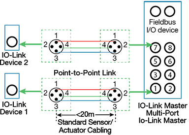
Figure 2: IO-Link controller/device interface
An IO-Link layer can be present on any given network. Installation of the IO-Link controller is possible within either the control cabinet, or directly in the field as a remote I/O with an industrial environment rated enclosure (IP65/67). The IO-Link device (any sensor, actuator, or combination of both) couples with the controller using a standard sensor/actuator cable, and transmits and receives data sent directly via IO-Link in a digital format. The following are highlights of IO-Link:
- The IO-Link standard states that sensor/actuator cables must have a length of 20 meters or less and be constructed from unshielded cables using standard connectors common to industrial systems. M8 and M12 connectors are in widespread use.
- Communication between controller and agent devices is half-duplex with three transmission rates: COM1: 4800 baud, COM2: 38.4 kbaud, and COM3: 230.4 kbaud. The IO-Link device only supports one data rate, while the IO-Link controller supports all three data rates.
- The IO-Link system supply range is 20V to 30V for the controller and 18V to 30V for the device (sensor or actuator).
a) IO-Link Pin Definitions
IO-Link is a standard for SDCI (single-drop communication interface), as described in IEC-61131-9, that maintains backward-compatibility with binary sensors. There are two port classes for the connectors, class A and class B. Port class A comprises 4 pins, as illustrated in Figure 3. The wiring for port class A uses three wires: (L+, L-, C/Q), with the fourth wire available as an additional signal line complying with IEC 61131-2. Its support is optional in both controller and devices.
Binary drivers use a standard 24V, 3-wire industrial interface. These drivers typically support high-side (PNP), low-side (NPN), or push-pull configurations along with normally open (NO) or normally closed (NC) logic.

| Pin | Signal | Designation |
|---|---|---|
| 1 | L+ | Power supply (+) |
| 2 | I/Q | NC/DI/DO (port class A) P24 (port class B) |
| 3 | L- | Power supply (-) |
| 4 | C | "Switching signal" (SIO) |
| Q | "Coded switching" (COM1, COM2, COM3) |
Figure 3: Class A pin description
Figure 4 depicts a port class B connector. Class B connectors have 5-wire connections (L+, P24, L-, C/Q, N24). These are present in devices that need additional power from an independent 24V supply.

| Pin | Signal | Designation |
|---|---|---|
| 1 | L+ | Power supply (+) |
| 2 | I/Q P24 | NC/DI/DO (port class A) P24 (port class B) |
| 3 | L- | Power supply (-) |
| 4 | C/Q | SIO/SDCI |
| 5 | NC N24 |
NC (port class A) N24 (port class B) |
Figure 4: Class B pin description
Communication can take place using standard I/O (SIO) or SDCI bidirectional communication modes. SIO mode ensures backwards compatibility with existing sensors. IO-Link mode provides bidirectional communication. Data is transmitted over the CQ line using nonreturn-to-zero (NRZ) modulation; logic 0 is 24V between C/Q and L- and logic 1 is 0V between C/Q and L-. In IO-Link mode, pin 2 can operate in DI mode as a digital input, DO mode as a digital output, or not connected (NC).
b) Data Types
Figure 5 illustrates the initiation of communication between the controller and device; all communication must start with a request from the controller and after that, follow a fixed schedule. The device must answer all requests from the controller. A back-and-forth communication sequence is called an M-sequence (message sequence) and can take many different forms, varying in total length. All data communication uses a UART frame, consisting of 11 bits = 1 start bit + 8 data bits + 1 parity bit + 1 stop bit.
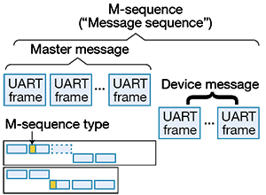
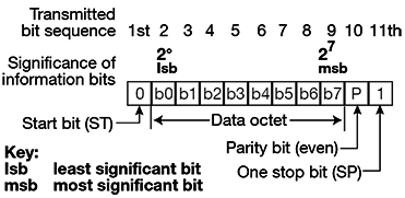
Figure 5: IO-Link Controller-Device communication sequence
To configure a device or communicate with it for the first time, the controller sends a wake-up request. When the wake-up request is received, the device configures itself to receive mode. The second step involves establishing the data rate for communication. The controller sends multiple messages over the range of data rates from fastest to slowest, waiting for the device to respond after each send. The device responds to the message sent at its own data rate. All IO-Link devices must have an associated IO-Link device description (IODD) file, an XML file that is used by the controller for identification, data interpretation, and configuration of the device.
IO-Link data communication can be cyclic or acyclic. Cyclic communication consists of data that is transmitted during regular operation, and include process data and measurements from the sensor. Acyclic data is on-request and can contain configuration or maintenance information, event-triggers (like notifications, warnings, errors), service data for large data structures, and page data for direct reading of device parameters.
4. Analysis
Designing an IO-Link Sensor
The IO-Link communication protocol allows smart sensors to work with IO-Link controllers. Figure 6 illustrates the basic structure of an IO-Link sensor. Some of the questions the system designer must consider are:
- What type of sensor(s) is/are being integrated (optical, temperature, etc.)?
- Which MCU is interfacing with the sensor and running the IO-Link device stack?
- What is the IO-Link transceiver (or physical layer/PHY) being used?
- What are the various voltage and current ratings required?
- What connector types are being used?
- What external protection (TVS for surge, EFT/burst, ESD, etc.) is required?
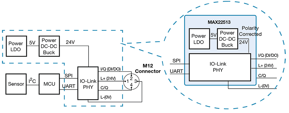
Figure 6: Building blocks of an IO-Link sensor
5. Reference Designs from Maxim Integrated
In IO-Link applications, the IO-Link device transceiver serves as the microcontroller's physical layer (PHY) interface. The transceiver runs the data-link layer protocol and supports digital inputs and outputs at voltages up to 24V. Maxim transceivers are capable of supporting IO-Link specifications at very low power dissipation levels; the third-generation MAX14828 single-channel transceiver and the MAX14827A dual-channel transceiver dissipate only 70mW when driving a 100mA load. In addition, Maxim’s latest IO-Link transceiver, the MAX22513, features a selectable control interface, an internal high-efficiency DC-DC buck regulator, two internal linear regulators, and integrated surge protection.
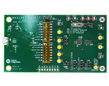
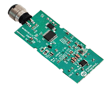
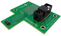
1. Temperature sensor reference design - MAXREFDES164
Figure 7 depicts the block diagram for the MAXREFDES164 temperature sensor reference design. The MAXREFDES164 is a collaborative product from Technologie Management Gruppe Technologie und Engineering (TMG TE), Maxim, and TEConcept. The design comprises a Maxim IO-Link device transceiver (MAX14828), a MAX32660 ultra-low-power 32-bit microcontroller using TMG TE's or TEConcept's IO-Link device stack, and a Maxim local temperature sensor (MAX31875).
Due to its minimal power requirements, small form factor, and low cost, the MAXREFDES164 IO-Link local temperature sensor is well-suited to industrial control and automation applications.
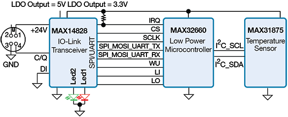
Figure 7: MAXREFDES164 IO-Link temperature sensor block diagram
The MAX14828 is a small form factor (2.5mm x 2.5mm) IO-Link device transceiver that is compliant with the IO-Link version 1.1.3/1.0 physical layer. The MAX14828 features two ultra-low-power drivers with active reverse-polarity protection. Operation is specified for typical 24V supply voltages, supporting a maximum of 60V. An SPI interface is available and for IO-Link operation, a three-wire UART interface is provided. The MAX14828 includes integrated 3.3V and 5V linear regulators, which provide the low-noise supply rails for the other components on the board.
The MAX32660 is an ultra-low-power, cost-effective, highly integrated microcontroller. It combines a flexible and versatile power management unit with an Arm® Cortex®-M4 with a floating-point unit (FPU). The device integrates up to 256KB of flash memory and 96KB of RAM to accommodate application and sensor code. It supports SPI, UART, and I2C communication.
The MAX31875 is a ±1°C-accurate local temperature sensor with an I2C/SMBus interface. The I2C-compatible two-wire serial interface allows access to conversion results, and standard I2C commands can be used for configuration and reading data.
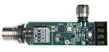
2. Distance sensor reference design - MAXREFDES171
Figure 8 depicts the MAXREFDES171, a distance sensor reference design. The MAXREFDES171 consists of an MAX22513 IO-Link device transceiver, a MAX32660 ultra-low-power 16-bit microcontroller utilizing the TMG TE IO-Link device stack, and a VL53L1 time-of-flight (ToF) laser-ranging distance sensor. The design is compliant with the IO-Link version 1.1.3/1.0 standard.
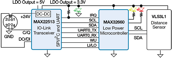
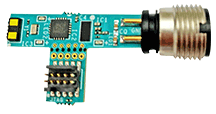
Figure 8: MAXREFDES171 IO-Link device distance sensor
The MAX22513 is an IO-Link device transceiver, complying with the IO-Link version 1.1/1.0 physical layer specification. The high-voltage components often found in industrial sensors are integrated, including drivers, a high-efficiency DC-DC buck regulator, and two linear regulators. All four IO pins (V24, C/Q, DO/DI, and GND) have built-in reverse-voltage and short circuit protection, and feature integrated 1kV/500Ω surge protection. External transient protection can be simplified due to the transceiver’s high voltage tolerance (65V absolute maximum rating) and integrated surge protection. The integrated DC-DC buck regulator in MAX22513 provides the 3.3V and 5V rails, and delivers a load current of up to 300mA. The MAX22513 features a flexible control interface, allowing control through either an SPI or I2C interface. I2C allows both the MAX22513 and the sensor IC to be on the same bus. A 3-wire UART interface is provided to facilitate IO-Link operation. Because of the integrated surge protection within the MAX22513 at the IO-Link interface, the MAXREFDES171 does not require external protection, such as varistors or TVS diodes.
The MAX32660 is an ultra-low-power, cost-effective, highly integrated microcontroller, featuring a powerful Arm® Cortex®-M4 with FPU. The device offers up to 256KB of flash memory and 96KB of RAM to accommodate applications and sensor code. It supports SPI, UART, and I2C communication and comes in a tiny form factor.
The VL53L1X is a ToF laser-ranging sensor that provides accurate distance measurements up to 400cm.
6. Glossary
- Acyclic data: Data that is transmitted from the controller only after a request. This includes data such as configuration and diagnostic information.
- Analog Front End (AFE): The analog portion of a circuit which precedes A/D conversion.
- COM1-3: The available rates that IO-Link data is transmitted. There are three available data rates: COM1: 4800 baud, COM2: 38.4 kbaud, and COM3: 230.4 kbaud.
- Cyclic data: Data that is transmitted by the controller automatically and at regular intervals. This includes data such as process data and value status.
- IEC 61131-9: The International standard listing specifications for programmable controllers. IO-Link is described in part 9:
Single-drop digital communication interface for small sensors and actuators (SDCI). - IODD (IO-Link Device Description): An electronic description of an IO-Link device’s specifications. An IODD file is required for every IO-Link device. IODD is represented in XML format and contains the necessary properties to establish communication with the device, the device’s parameters, identification information, process and diagnostic information, an image of the device, and the manufacturer’s logo.
- IO-Link device: A field device that is monitored and controlled by an IO-Link controller.
- IO-Link controller: The device that represents the connection between a higher-level PLC/controller and IO-Link devices. The IO-Link controller monitors and controls the IO-Link devices.
- Non Return to Zero (NRZ): A binary encoding scheme in which ones and zeroes are represented by opposite and alternating high and low voltages, and where there is no return-to-zero (reference) voltage between encoded bits. That is, the stream has only two values: low and high.
- Port: A port is an IO-Link communication channel.
- Sensor: A device that detects a physical parameter, such as temperature, motion, light, or sound, and converts it to an electrical signal that can be measured and used by an electrical or electronic system.
- Serial Interface: An interface in which data is sent in a single stream of bits, usually on a single wire-plus-ground.
Related Components
IO-Link is a standard for industrial networking (IEC 61131-9) that enables bidirectional communication between devices, such as sensors, actuators, and controllers. The IO-Link standard also specifies backwards compatibility with legacy sensors and actuators, enabling smart functionality in existing systems. Maxim Integrated offers several reference designs featuring full IO-Link compatibility.
Buy Now
Buy Now
Buy Now
Buy Now
Buy Now
For more IO-Link sensors products. Shop Now
Take the Quiz
Sensors VIIII
Are you ready to demonstrate your IO-Link sensors knowledge? Then take this 10-question quiz. To earn the Sensors IX Badge, read through the module, attain 100% in the quiz, and leave us some feedback in the comments section.


