Voltage and current measurements are indispensable in electrical and electronic testing and evaluation. A digital multimeter (DMM) performs these functions in the electronics, high energy physics, semiconductors, biological electronics, and other related fields. Generally, any device's performance testing needs a power supply to power up that machine and a DMM to simultaneously measure the voltage and current. A standard DMM is a single function instrument and cannot measure voltage and current simultaneously. Two DMMs are thus necessary for a single setup. In contrast, a source measure unit (SMU) is a single instrument capable of sourcing and measuring current and voltage with high accuracy and resolution concurrently, in a precise and straightforward setup. SMUs offer integrated features, help to maximize speed, and swiftly accomplish the job. This learning module will explore the basic concepts of SMUs, their functionality, and some use case applications.
2. Objectives
Upon completion of this module, you will be able to:
 Explain the basic concepts of SMUs with key specifications
 Discuss Tektronix/Keithley SMUs, their features, and their patented TSP
 and TSP-Link
Technology
 Discuss measurement applications with a few Tektronix/Keithley SMUs
A SMU is a multifunctional, multipurpose tool. For a bench, it can be a five-in-one instrument acting as a Power Supply, Digital Multimeter (DMM), Electronic Load, Current Source, and a pulse generator, all packed into a single, tightly synchronized instrument in a compact form factor. SMU instruments are typically used for test applications like current-voltage (I-V) characterization of semiconductor components, structures, and materials where both voltage and current need to be controlled across positive and negative values. Such applications need high accuracy, measurement flexibility, and high resolution. For example, the forward conduction and reverse leakage performance in a simple electronic diode must be accurately characterized to produce a high-quality diode. An ideal diode allows current to flow in one direction, but does not allow any current to flow in the reverse. In practice, a very small amount of current is always allowed, and precisely measuring this current can be important. SMUs can function as a bench instrument similar to a curve tracer for characterization purposes, or in a mounted rack for automated testing.
The advantage of using a single SMU instrument over a DMM and power supply combination lies in reducing the synchronization, connection, and programming issues inherent in using multiple instruments. SMUs have built-in functionality for accomplishing tasks you would typically need to spend time programming with a DMM/power supply combination. Measuring resistance or power, sweeping voltage or current, or even pulsing are very simple with a SMU. SMUs also provide complete accuracy specifications with various error terms from sources and measurement sections.
Another key SMU advantage is simplified wiring and reduced table space requirements. The SMU instrument facilitates multiple I-V characterization tests, including simple forward and reverse signal diode tests, IC leakage, LEDs, and PV Cells tests. They are used in automatic test equipment, and usually have an interface like USB or GPIB to connect to a computer. This learning module's scope is limited to the SMU product range of Keithley (Tektronix), their basic concepts, working operation, an analysis of the testing procedure, and some use case applications.
A SMU offers four functions in a single instrument: source current, source voltage, measure current, and measure voltage. Figure 1 shows the schematic of a SMU with the force functions in red and the measure functions in blue. Only one source function can be active at a time. Depending on the SMU, either one or both measure functions can be active simultaneously.
The selection of either local or remote dictates the voltage measurement or sense location. The voltage is measured locally between Force HI and Force LO terminals (sometimes called Source HI and Source LO). In a remote sense (aka Kelvin or 4-wire mode), the voltage is measured between Sense HI and Sense LO terminals. These Sense terminals can be placed at the test device, eliminating any voltage drops caused by current flowing through test lead resistance.
The instrument, when configured to Source Voltage and Measure Current, works as a low impedance voltage source with current and voltage measurements and current limit capability. Sense circuitry continuously monitors the output voltage and adjusts the voltage source. When configured to Source Current and Measure Voltage, the SMU behaves like a high impedance current source, but retains its other abilities.
These instruments have four-quadrant source functionality and offer sink capability for electronic loads. A four-quadrant source implies a bipolar power supply and may produce positive or negative voltages spanning their output terminals without changing the terminals' external wiring. Figure 2 illustrates the SMU's four-quadrant functionality.
In quadrants 1 and 3, the SMU works as a power supply to source power with respective positive and negative voltage. The current flow exits the more positive voltage terminal. In quadrants 2 and 4, the SMU works as load, and consumes power as current flows into the more positive voltage terminal.
- 4.1 SMU Characteristics
The characteristics of SMUs make them suitable for low-level measurements. For example, they provide high input resistance, minimizing circuit load when voltage measurements are made from high impedance sources. Their current measurement sensitivity can be as low as 10aA, a current equivalent to a net flow of about 60 electrons/second. A SMU with Triax connectors allows minute low noise measurements.
Sweep capabilities are a notable advantage of SMU instruments. Current or voltage can be swept across the necessary range at particular increments, and the resulting voltage or current is measured at every step. Integrated source-delay-measure cycles permit measurement speed optimization, while ensuring sufficient circuit settling time to maintain measurement integrity. Some SMUs come with pulsing capabilities. SMUs can make ideal pulsed power supplies or loads, due to their inherent speed advantage over typical power supplies.
Because SMUs can measure voltage and current at the same time, it is trivial for them to measure power (voltage times current) and resistance (voltage divided by resistance). Most SMUs have the option to directly return measurements of power and resistance. In measuring resistance, SMUs have an advantage over standard DMMs, in that they can choose to source either voltage or current while measuring the other. DMMs will only measure resistance by sourcing current. However, SMUs may not always give you specifications for power or resistance measurements, so you must understand SMU specifications.
- 4.2 Understanding SMU Specifications
A proper comprehension of SMU specifications is essential to make useful low-level measurements. Instrument accuracy is most likely the crucial specification, but several other factors are considered, including noise, deratings, and speed.
Accuracy
Accuracy is essential, and instrument accuracy is paramount. Multiple factors affect accuracy. Instrument accuracy is specified in numerous ways, including a percentage of reading, percentage of full scale, or a blend of both. Other factors include input loading, leakage resistance, electrostatic interference, and thermoelectric EMFs. Accuracy is usually expressed with unit percentage (%), parts per million (ppm), counts, and so on.
Calculating Resistance Measurement Accuracy Using A SMU Instrument
The summation method is used for SMUs when the source's accuracy and the measurements' accuracy are found independently and then computed together. In such a case, the uncertainty calculation of a 20Ω resistor with 100mA test current includes both current and voltage measurement accuracy specifications:
Current Measure Accuracy:
Output Signal = 100 mA on 100mA range (this is what the SMU is sourcing)
Accuracy Specification = ±(0.055% of reading + 6µA)
Error% = ±0.061%
Voltage Measure Accuracy:
Measured Signal = (20Ω x 100 mA) = 2 V
Accuracy Specification of 2V Range = ±(0.012% of reading + 300µV)
Error% = ±0.027%
Total resistance uncertainty = ±(0.061% + 0.027%) = ±0.088%
Deratings
Accuracy parameters are subject to deratings for temperature and time drift. The temperature of the operating environment may influence accuracy. Thus, instrument specifications are usually given over a defined temperature range. Keithley (Tektronix) accuracy specifications on newer SMU instruments are generally offered over an 18°C to 28°C range. For temperatures exceeding this range, a temperature coefficient such as ±(0.005 % + 0.1 counts)/°C or ±(5ppm of reading + 1ppm of range)/°C is specified.
Noise and Noise Rejection
Noise is considered when making any electronic measurement, but the noise problem can be particularly severe in low-level measurements. Thus, noise specifications must be well understood when evaluating the performance of an instrument.
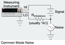
Normal mode noise is an error signal that adds to the desired input signal. It is detected as a peak noise or deviation in a DC signal. The normal mode rejection ratio (NMRR) describes the instrument's efficiency in rejecting or attenuating noise found between the LO and HI input terminals. The integrated A/D converter is used to attenuate noise. Careful shielding usually attenuates normal mode noise, and many instruments have internal filtering to further reduce the effects of such noise.
Figure 3: Normal Mode Noise and Common Mode Noise
The common-mode rejection ratio (CMRR) specifies an instrument's capability in rejecting noise signals found between both input high and input low, as well as chassis ground. CMRR is generally measured with a 1kW resistor imbalance in one of the input leads. To minimize common-mode noise, connect electrical shields to a single point in the test system. NMRR and CMRR are specified in dB at 50 and 60Hz - the interference frequencies of most significant interest.
Speed
Instrument measurement speed is vital in many test situations, more so in measurements from low impedance devices. It is usually specified as an exact number of readings per second for given operating conditions. Certain factors, such as the integration period and amount of filtering, may influence overall instrument measurement speed. However, changing these operating modes may also alter resolution and accuracy, implying a trade-off between accuracy and measurement speed.
Keithley (Tektronix) offers a range of SMUs, such as the 2400 Graphical Series, 2600B System SourceMeter series, and the 2650 High Power SMU series. They can source and measure a large range of current and voltage with high precision, accuracy, and wide dynamic range. The patented TSP
and TSP-Link
technologies execute complete test programs inside the SMU, to deliver optimal performance and enable expansion of up to 64 channels for high-speed, SMU-per-pin parallel testing without a mainframe. We will discuss some SMUs from these series with their working functionality, characteristics, and a few use case applications.
- 5.1 The 2460 Graphical SourceMeter SMU
Keithley's (Tektronix) 2460 is a High Current SourceMeter SMU having the flexibility to source/sink high current and measure voltage and current. It is a perfect solution for measuring low resistance devices that require stimulus currents up to 7A. The resistance is calculated automatically. Integrated features like offset compensation and remote sensing assist in optimizing low resistance measurements with <1mΩ resolution.
Measuring Low Resistance Devices with High Current Using the 2460 SMU:
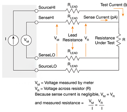
Low resistance measurements easily identify resistance elements that have transformed over time. Such a measure evaluates material degradation due to environmental factors like heat, fatigue, corrosion, and vibration. It is employed to assess circuit breakers, high power resistors, cables and connectors, switches, bus bars, and other conductive elements. Figure 4 shows a setup for low resistance measurement using the front panel connections Source HI, Sense HI, Source LO, and Sense LO. The connection facility is also available on the rear panel of the instrument. The following are the familiar sources of error in low resistance measurement and methods to minimize these errors.
Lead Resistance:
The addition of total lead resistance (RLEAD), which ranges from 1mΩ to 10mΩ, creates a problem when the two-wire technique for low resistance measurements is used. Thus, it is fiendishly complex to obtain precise two-wire resistance measurements if the resistance being tested is lower by 10Ω to 100Ω (contingent on load resistance). The four-wire (Kelvin) connection method, as shown in Figure 4, is generally preferred to minimize this error.
The test current (I), in this configuration, is forced through test resistance (R) via the outer set of test leads, while voltage (VM) spanning the Resistance Under Test gets measured via a second set of leads termed sense leads. Although a minute current may proceed through these sense leads, it is generally negligible (on the order of nA), and thus there is a trivial voltage drop spanning the sense leads. The meter (VM) reads the same voltage (VR) across the resistance (R). It is recommended that the voltage-sensing leads should be connected as close to the resistance under test as possible to avoid as much lead resistance as possible.
Thermoelectric Voltages:
Thermoelectric EMFs generate when different parts of a circuit are at different temperatures and conductors made of different materials are joined together. Temperature gradients also create a few microvolts in the test circuit, caused by fluctuating temperatures in the lab or a draft near the sensitive circuitry.
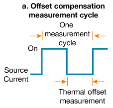
Figure 5: Offset-compensated ohms method
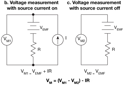
The offset-compensated ohms method is used to minimize the thermoelectric EMFs, as shown in Figure 5a. The source current gets applied to the resistance under measurement during a part of the cycle. The instrument's total voltage (Figure 5b), in the presence of source current, includes the resistor spanning voltage drop and thermoelectric EMFs, if any. The source current is dialed to zero amps during the measurement cycle's second half, and the meter measures the sole voltage (Figure 5c). This voltage is the circuit's thermoelectric EMF. Since VEMF is precisely measured during the cycle's second half, it is subtracted from the voltage measurement done during the cycle's first half, so the offset-compensated voltage measurement takes the form:
VM = VM1 - VM2
VM = (VEMF + IR) - VEMF
VM = IR and,
R = VM / I
Non-Ohmic Contacts:
Non-ohmic contacts are prominent when the contact's potential difference spanning the contact is not linearly proportional to the current flowing across it. There are possibilities of Non-ohmic contacts in any low voltage circuit, thanks to nonlinear connections like oxide films. Select the appropriate contact material to prevent all non-ohmic contacts, for example indium or gold. The SMU instrument's compliance/limit voltage must be sufficiently high to sidestep problems arising from the source contact's non-linearity. Use appropriate grounding and shielding to reduce AC pickup and minimize error from voltmeter non-ohmic contacts.
Device Heating:
Low resistance measurements use test currents that are considerably higher than currents utilized for high resistance measurements. It implies that device power dissipation can be significant if it is sufficiently high as to cause changes in the device's resistance value. This formula gives power dissipation in a resistor:
P = I2R.
This relationship reveals that each time the current doubles, the power dissipated in the device increases four times. Thus, to minimize this effect, the lowest possible current must be used, to maintain the desired voltage across the DUT. If the current can be reduced, use a narrow current pulse instead of a DC signal.
- 5.2 The 2450 SourceMeter SMU:
The 2450 is Keithley's industry leading graphical SourceMeter SMU and is used for Ohm's law (current, voltage, and resistance) testing. The graphical user interface (GUI) and advanced, capacitive touchscreen technology allows intuitive use and minimizes the learning curve. The centerpiece of this SMU comprises the capabilities of analyzers, curve tracers, and I-V systems, with 0.012% measure accuracy with a 6½-digit resolution, enhanced sensitivity with new 20mV and 10nA source/measure ranges. It is also able to function in SCPI and TSP
scripting programming modes.
I-V Characterization of Photovoltaic Cells Using the 2450 SMU:
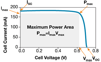
Photovoltaic (PV) or solar cell devices absorb photons from any appropriate light source and consequently release electrons, thus causing an electric current flow when the cell gets connected to a load. PV cells and panels manufacturers engage in R&D to achieve the highest possible efficiency. During the R&D and manufacturing process, the cell's electrical characterization and the PV materials are determined. The cell's current-voltage (I-V) characterization is performed to derive crucial parameters concerning the cell's performance, including its voltage (Vmax) and maximum current (Imax), open-circuit voltage (VOC), short circuit current (ISC), and its efficiency (η). Other common measurements are shunt resistance (RSH), Conversion efficiency (η), Maximum power output (Pmax), Voltage at Pmax (Vmax), Resistivity, Fill factor (ff), and Series resistance (Rs).
The three parameters used to describe a solar cell comprise maximum power point (Pmax), short circuit current (ISC), and open-circuit voltage (VOC). All three are illustrated in Figure 6, which depicts an illuminated solar cell's typical forward bias I-V curve. The maximum power point (Pmax) is the product of voltage (Vmax) and maximum cell current (Imax). It is where the cell's power output is maximum. This point is found at the curve's "knee."
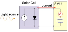
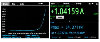
Figure 7 shows a setup with the 2450 SourceMeter SMU in use for I-V characterization of a solar cell, with a graphical display for both the I-V curve of a forward bias solar cell or solar panel and the three parameters: maximum power (Pmax), short circuit current (Isc), and open-circuit voltage (VOC).
Figure 7: Circuit diagram with 2450 SMU with graphical display I-V curve (Source: I-V Characterization of Solar Cells and Panels/ ApplicationCards.pdf)
- 5.3 The 2600B System SourceMeter SMU:
Keithley's Series 2600B System SMU instruments are reliable current-voltage sources and measure solutions for highly automated, sophisticated production test applications. They integrate a precision power supply, current source, DMM, and electronic load with pulse generating capabilities. TSP technology runs complete test programs inside the SMU for fully automated system applications. The TSP-Link
technology sanctions daisy-chaining a maximum of 64 channels for profuse parallel tests.
TSP and TSP-Link
Technology:
Test Script Processors (TSP) is an extremely flexible hardware/software architecture that permits many different implementation choices. The primary trade-off is programming complexity versus throughput. Relatively simple programming techniques allow noticeable throughput improvements. Slightly more complex programming can produce significantly higher throughput gains. It will enable message-based programming with enhanced capabilities for controlling test sequencing/flow, decision-making, and instrument autonomy using user-defined test scripts.
TSP-Link is a high-speed trigger synchronization / inter-unit communication bus incorporated in TSP-based instruments. It is used to connect multiple instruments in a master/slave configuration. Once connected, all the TSP-Link equipped instruments in a system can be programmed and operated under the master unit or units' control. By serving as an external backplane without the need for a chassis/mainframe, TSP-Link provides virtually unlimited flexibility to scale a test system's channel count up or down, as the application requires, while ensuring seamless integration. Combining TSP-Link with a flexible programmable trigger model provides speed and accuracy. Master/slave operation (TSP-Link) produces faster test times.
Simplifying FET Testing with the 2600B System SourceMeter SMU:
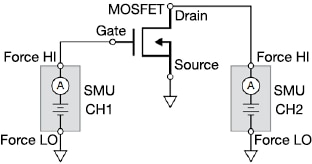
A FET's I-V characteristics are used to extract multiple parameters about the device, study the effects of fabrication techniques and process variations, and control the contacts' quality. Figure 8 illustrates a DC I-V test configuration for a MOSFET using a two-channel Series of 2600B SMU. In this configuration, the Force HI terminal of Channel 1 is connected to the MOSFET gate, while the Force HI terminal Channel 2 is connected to the drain. The source terminal of the MOSFET is connected to the Force LO terminals of both SMU channels and a third SMU, if necessary, to source and measure all three terminals of the MOSFET.
Figure 8: MOSFET test configuration using two SMU channels (Source: SimplifyFET-Testing_AppNote)
The drain family of curves (VDS-ID) is a standard I-V test done on a MOSFET. This test enables SMU CH1 to step gate voltage (VG), while the SMU CH2 sweeps drain voltage (VD) and also measures the resulting drain current (ID). When the two SMUs are configured to perform the test, the data can be generated and plotted on the screen in real-time. I-V data can be exported directly to a .csv file and then imported into a spreadsheet for further analysis. This can also be displayed in a table view.
KickStart Software
KickStart Instrument Control Software lets you start making measurements in minutes without complex instrument programming. KickStart allows you to do I-V characterization, data acquisition, logging, and power supply control on a variety of Keithley products. KickStart simplifies what you need to know about the instrument, so that in minutes you can take the instrument out of the box and get real data on your device. By plotting data immediately and offering quick statistical summaries of the data in the reading table, KickStart allows you to gather insights faster and make the decisions you need to move on to the next stage of device development. The software saves you time by facilitating quick replication of tests and comparison of results using convenient export features. KickStart Software for the PC enables quick test setup and data visualization when using multiple instruments.
 Save time by automating data collection of millions of readings.
 Set up a multi-instrument test with the ability to independently control up to eight instruments.
 Supports source measure unit (SMU) instruments, DMMs, power supplies, oscilloscopes, dataloggers, and sensitive instruments. Replicate tests quickly using saved test configurations.
 Use built-in plotting and comparison tools to quickly discover measurement anomalies and trends.
 Auto-export data in ready-to-use .csv and .xlsx formats for reports and additional analysis.
 Sensitivity: The smallest change in a signal that can be detected by the instrument.
 Resolution: This is the smallest portion of a signal that the instrument can observe.
 Reproducibility: The closeness of agreement between measurements of the same quantity with a stated change in conditions.
 Repeatability: The closeness of agreement between consecutive measurements with the same conditions.
 Absolute accuracy: This is the closeness of agreement between the result of a measurement and its true value, taking into account the standard value's uncertainty.
 Relative accuracy: This is the closeness of agreement between the result of a measurement and its true value or accepted standard value, without taking the standard value's uncertainty into account.
 Error: The deviation of a measurement from its true value.
 Random error: The mean of many measurements influenced by random error matches the true value.
 Systematic error: The mean of many measurements influenced by systematic error deviates from the true value.
 Uncertainty: This is an estimate of the bounded interval around the measured value, which is likely to contain the true value.
 MOSFET: Metal Oxide Field Effect Transistor
 A/D Converter: Analog to Digital Converter
*Trademark. Keithley is a trademark of Tektronix Inc. Other logos, product and/or company names may be trademarks of their respective owners.
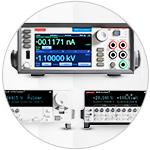
Shop our wide range of Source Measure Units, including Standard SMUs, Graphical Touchscreen SMUs, Single or Dual Channel Systems SMUs, High Power SMUs, High Density SMUs, Optical SMUs, and more.
Test Your KnowledgeBack to Top
Are you ready to demonstrate your Source Measure Unit (SMU) knowledge? Then take a quick 15-question multiple choice quiz to see how much you've learned. To earn the Tools & Test Equipment II Badge, read through the module to learn all about Source Measure Units (SMUs), attain 100% in the quiz at the bottom, leave us some feedback in the comments section, and give the module a star rating.



Top Comments
-

phoenixcomm
-
Cancel
-
Vote Up
0
Vote Down
-
-
Sign in to reply
-
More
-
Cancel
Comment-

phoenixcomm
-
Cancel
-
Vote Up
0
Vote Down
-
-
Sign in to reply
-
More
-
Cancel
Children