element14 Community
element14 Community
    Register Log In
  • Site
  • Search
  • Log In Register
  • Community Hub
    Community Hub
    • What's New on element14
    • Feedback and Support
    • Benefits of Membership
    • Personal Blogs
    • Members Area
    • Achievement Levels
  • Learn
    Learn
    • Ask an Expert
    • eBooks
    • element14 presents
    • Learning Center
    • Tech Spotlight
    • STEM Academy
    • Webinars, Training and Events
    • Learning Groups
  • Technologies
    Technologies
    • 3D Printing
    • FPGA
    • Industrial Automation
    • Internet of Things
    • Power & Energy
    • Sensors
    • Technology Groups
  • Challenges & Projects
    Challenges & Projects
    • Design Challenges
    • element14 presents Projects
    • Project14
    • Arduino Projects
    • Raspberry Pi Projects
    • Project Groups
  • Products
    Products
    • Arduino
    • Avnet Boards Community
    • Dev Tools
    • Manufacturers
    • Multicomp Pro
    • Product Groups
    • Raspberry Pi
    • RoadTests & Reviews
  • Store
    Store
    • Visit Your Store
    • Choose another store...
      • Europe
      •  Austria (German)
      •  Belgium (Dutch, French)
      •  Bulgaria (Bulgarian)
      •  Czech Republic (Czech)
      •  Denmark (Danish)
      •  Estonia (Estonian)
      •  Finland (Finnish)
      •  France (French)
      •  Germany (German)
      •  Hungary (Hungarian)
      •  Ireland
      •  Israel
      •  Italy (Italian)
      •  Latvia (Latvian)
      •  
      •  Lithuania (Lithuanian)
      •  Netherlands (Dutch)
      •  Norway (Norwegian)
      •  Poland (Polish)
      •  Portugal (Portuguese)
      •  Romania (Romanian)
      •  Russia (Russian)
      •  Slovakia (Slovak)
      •  Slovenia (Slovenian)
      •  Spain (Spanish)
      •  Sweden (Swedish)
      •  Switzerland(German, French)
      •  Turkey (Turkish)
      •  United Kingdom
      • Asia Pacific
      •  Australia
      •  China
      •  Hong Kong
      •  India
      •  Korea (Korean)
      •  Malaysia
      •  New Zealand
      •  Philippines
      •  Singapore
      •  Taiwan
      •  Thailand (Thai)
      • Americas
      •  Brazil (Portuguese)
      •  Canada
      •  Mexico (Spanish)
      •  United States
      Can't find the country/region you're looking for? Visit our export site or find a local distributor.
  • Translate
  • Profile
  • Settings
STEM Academy
  • Learn
  • Learning Center
  • STEM Academy
  • More
  • Cancel
STEM Academy
Blog TI-PMLK Buck Experiment Board - part 1b: 1st Experiment Lab Setup
  • Blog
  • Forum
  • Documents
  • Events
  • Polls
  • Files
  • Members
  • Mentions
  • Sub-Groups
  • Tags
  • More
  • Cancel
  • New
Join STEM Academy to participate - click to join for free!
  • Share
  • More
  • Cancel
Group Actions
  • Group RSS
  • More
  • Cancel
Engagement
  • Author Author: Jan Cumps
  • Date Created: 24 Jun 2017 12:21 PM Date Created
  • Views 2666 views
  • Likes 7 likes
  • Comments 7 comments
  • buck
  • stem
  • tps54160
  • texas_instrments
  • road_test
  • stem projects
  • ti_rt
Related
Recommended

TI-PMLK Buck Experiment Board - part 1b: 1st Experiment Lab Setup

Jan Cumps
Jan Cumps
24 Jun 2017

I am a Road Tester of the TI-PMLK Buck Experiment Board: TPS54160 & LM3475.

It's an educational kit - board and book - to learn buck converter theory and practice.

Because it's an educational kit, I give minus points each time there's vendor lock-in image .


image


I applied for the Road Test to check the educational value of the kit. The focus in this blog series will be on the Lab Manual and exercises.

In this blog, I set up the test equipment for Experiment 1


Experiment 1: Impact of Load, Input Voltage and Switching Frequency on Efficiency


In this exercise we'll measure the efficiency a few times under changing conditions.

The tutorial advises this Lab setup:

image

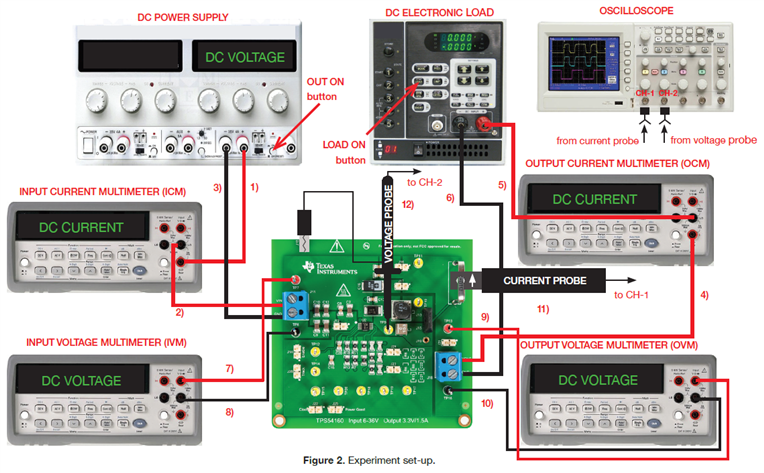
I'm replacing the input current meter with the display of my power supply. The input voltage I've measured with the DMM.

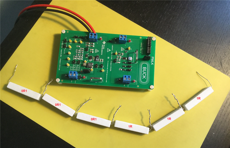
The load is a string of 0R1 and R resistors that form 3R3 in total. That's 1A of output current for this 3V3 circuit.


image

My biggest miss is a current probe. This is used in the circuit to measure the current racing trough the inductor.

I first tried if I could put two oscilloscope probes on TP10 and TP11 of the circuit.


image

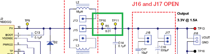
Then I tried to use the Math function of my scope to show the difference between the two.

It turns out (as expected really) that I don't get enough drop over 0R01 resistor R5 to get a signal that's above the noise floor.


What works better is the second thing I tried: wind a coil of isolated wire around R5 and try to steal the current that way.

image

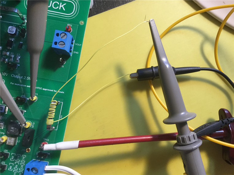
This works way better. I can get a view of the current in the circuit's switching node on my oscilloscope.

Way too course to do a good measurement but it does the job of visualising what happens.

The switch node current is the blue trace on the capture below:

image

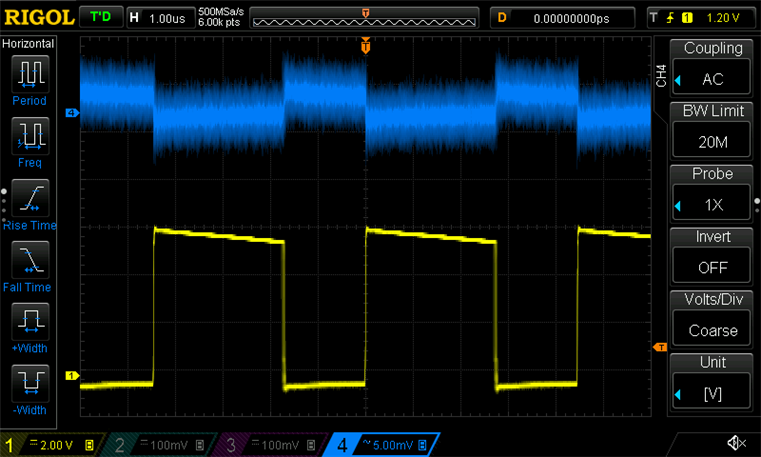
If you have a better idea on how I can show the switch node current, please comment below.


I measure output voltage with the DMM, and output current by putting my DMM over one of the load resistors in the chain + Ohm's Law.

(in the next blog you can see that I stepped away from measuring current over a series resistor and used a current meter. See comments below)


Related Blog
1a: 1st Experiment Set-up
1b: 1st Experiment Lab Setup
1c: 1st Experiment Measure
2: Educational Value

Road Test: TI-PMLK Buck Experiment Board: TPS54160 & LM3475

  • Sign in to reply

Top Comments

  • balearicdynamics
    balearicdynamics over 8 years ago +1
    Hi Jan, my compliments! Very well documented experiment. This is perfect as STEM. I have an ignorant question. In the scheme both two input and output current multimeters have only the current signal connected…
  • Jan Cumps
    Jan Cumps over 8 years ago in reply to balearicdynamics +1
    Enrico, Enrico Miglino wrote: ... In the scheme both two input and output current multimeters have only the current signal connected and not the ground (or negative). Can you explain this detail please…
  • balearicdynamics
    balearicdynamics over 8 years ago in reply to Jan Cumps +1
    Thank you Jan. As you can see my knowledge in the powering world is really terrible ! Just a note instead. I have used 1 Ohm 150 W resistors to calculate the current. I thought that it was a very crap…
  • balearicdynamics
    balearicdynamics over 8 years ago in reply to Jan Cumps

    Jan, I saw. This depends on the power level range I suppose. With low powering the method seems working as there is not the heating risk. I have not cited this aspect but iti s true what you say about the dramatic temperature influence. I was thinking on few mA order. Or this occurs anyway?


    Enrico

    • Cancel
    • Vote Up +1 Vote Down
    • Sign in to reply
    • More
    • Cancel
  • Jan Cumps
    Jan Cumps over 8 years ago in reply to DAB

    Thank you Don.

    The 2 current probes required for this board are off-circuit. It's one of those inductive oscilloscope add-ons that you clamp on a wire and that shows the waveform on your oscilloscope.

    image


    With this amplifier:

    image

    • Cancel
    • Vote Up 0 Vote Down
    • Sign in to reply
    • More
    • Cancel
  • Jan Cumps
    Jan Cumps over 8 years ago in reply to balearicdynamics

    Enrico Miglino wrote:


    Thank you Jan. As you can see my knowledge in the powering world is really terrible !


    Just a note instead. I have used 1 Ohm 150 W resistors to calculate the current. I thought that it was a very crap method instead I see that you too are using something similar. So is it reliable ? It seems I have not adopted a so bad solution...


    Enrico

    In the next blog you can see that I stepped away from this method and used a current meter in series with the output. The drift of my resistors was way too high to get a decent current sample..

    After running warm (not even hot) my 1R power resistor measured up to 2R. So I had to change strategy.

    • Cancel
    • Vote Up +1 Vote Down
    • Sign in to reply
    • More
    • Cancel
  • DAB
    DAB over 8 years ago

    Great post Jan.


    Yes, without an in circuit current probe, you are stuck pulling off voltage measurements and estimating the current flow.


    DAB

    • Cancel
    • Vote Up +1 Vote Down
    • Sign in to reply
    • More
    • Cancel
  • balearicdynamics
    balearicdynamics over 8 years ago in reply to Jan Cumps

    Thank you Jan. As you can see my knowledge in the powering world is really terrible !


    Just a note instead. I have used 1 Ohm 150 W resistors to calculate the current. I thought that it was a very crap method instead I see that you too are using something similar. So is it reliable ? It seems I have not adopted a so bad solution...


    Enrico

    • Cancel
    • Vote Up +1 Vote Down
    • Sign in to reply
    • More
    • Cancel
>
element14 Community

element14 is the first online community specifically for engineers. Connect with your peers and get expert answers to your questions.

  • Members
  • Learn
  • Technologies
  • Challenges & Projects
  • Products
  • Store
  • About Us
  • Feedback & Support
  • FAQs
  • Terms of Use
  • Privacy Policy
  • Legal and Copyright Notices
  • Sitemap
  • Cookies

An Avnet Company © 2025 Premier Farnell Limited. All Rights Reserved.

Premier Farnell Ltd, registered in England and Wales (no 00876412), registered office: Farnell House, Forge Lane, Leeds LS12 2NE.

ICP 备案号 10220084.

Follow element14

  • X
  • Facebook
  • linkedin
  • YouTube