element14 Community
element14 Community
    Register Log In
  • Site
  • Search
  • Log In Register
  • Community Hub
    Community Hub
    • What's New on element14
    • Feedback and Support
    • Benefits of Membership
    • Personal Blogs
    • Members Area
    • Achievement Levels
  • Learn
    Learn
    • Ask an Expert
    • eBooks
    • element14 presents
    • Learning Center
    • Tech Spotlight
    • STEM Academy
    • Webinars, Training and Events
    • Learning Groups
  • Technologies
    Technologies
    • 3D Printing
    • FPGA
    • Industrial Automation
    • Internet of Things
    • Power & Energy
    • Sensors
    • Technology Groups
  • Challenges & Projects
    Challenges & Projects
    • Design Challenges
    • element14 presents Projects
    • Project14
    • Arduino Projects
    • Raspberry Pi Projects
    • Project Groups
  • Products
    Products
    • Arduino
    • Avnet & Tria Boards Community
    • Dev Tools
    • Manufacturers
    • Multicomp Pro
    • Product Groups
    • Raspberry Pi
    • RoadTests & Reviews
  • About Us
  • Store
    Store
    • Visit Your Store
    • Choose another store...
      • Europe
      •  Austria (German)
      •  Belgium (Dutch, French)
      •  Bulgaria (Bulgarian)
      •  Czech Republic (Czech)
      •  Denmark (Danish)
      •  Estonia (Estonian)
      •  Finland (Finnish)
      •  France (French)
      •  Germany (German)
      •  Hungary (Hungarian)
      •  Ireland
      •  Israel
      •  Italy (Italian)
      •  Latvia (Latvian)
      •  
      •  Lithuania (Lithuanian)
      •  Netherlands (Dutch)
      •  Norway (Norwegian)
      •  Poland (Polish)
      •  Portugal (Portuguese)
      •  Romania (Romanian)
      •  Russia (Russian)
      •  Slovakia (Slovak)
      •  Slovenia (Slovenian)
      •  Spain (Spanish)
      •  Sweden (Swedish)
      •  Switzerland(German, French)
      •  Turkey (Turkish)
      •  United Kingdom
      • Asia Pacific
      •  Australia
      •  China
      •  Hong Kong
      •  India
      • Japan
      •  Korea (Korean)
      •  Malaysia
      •  New Zealand
      •  Philippines
      •  Singapore
      •  Taiwan
      •  Thailand (Thai)
      • Vietnam
      • Americas
      •  Brazil (Portuguese)
      •  Canada
      •  Mexico (Spanish)
      •  United States
      Can't find the country/region you're looking for? Visit our export site or find a local distributor.
  • Translate
  • Profile
  • Settings
STEM Academy
  • Learn
  • Learning Center
  • STEM Academy
  • More
  • Cancel
STEM Academy
Blog TI-PMLK Buck Experiment Board - part 1c: 1st Experiment Measure
  • Blog
  • Forum
  • Documents
  • Events
  • Polls
  • Files
  • Members
  • Mentions
  • Sub-Groups
  • Tags
  • More
  • Cancel
  • New
Join STEM Academy to participate - click to join for free!
  • Share
  • More
  • Cancel
Group Actions
  • Group RSS
  • More
  • Cancel
Engagement
  • Author Author: Jan Cumps
  • Date Created: 24 Jun 2017 2:08 PM Date Created
  • Views 5016 views
  • Likes 6 likes
  • Comments 16 comments
  • ti-pmlk
  • stem
  • texas_instruments
  • road_test
  • stem projects
  • ti_rt
Related
Recommended

TI-PMLK Buck Experiment Board - part 1c: 1st Experiment Measure

Jan Cumps
Jan Cumps
24 Jun 2017

I am a Road Tester of the TI-PMLK Buck Experiment Board: TPS54160 & LM3475.

It's an educational kit - board and book - to learn buck converter theory and practice.

Because it's an educational kit, I give minus points each time there's vendor lock-in image .


image


I applied for the Road Test to check the educational value of the kit. The focus in this blog series will be on the Lab Manual and exercises.

In this blog, I measure the efficiency for Exercise 1.


Doing the measurements


This is where the educational value of the kit is really excellent. The book doesn't discuss Buck regulator theory or measurement principles.

It assumes you have those skills. I think that's a good starting position in this case.

If you don't understand Buck converters or lack the skill of using multimeters and oscilloscopes, it doesn't really make sense to do these experiments.

They build upon your knowledge. They are not the base for  it.


Goal of Experiment 1:

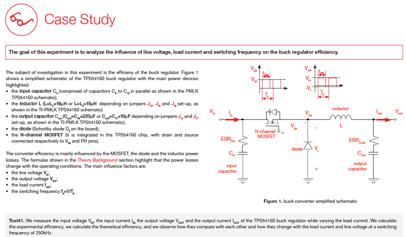
The goal of this experiment is to investigate how the efficiency of a buck regulator depends on the line and load conditions and on the switching frequency.


The document reviews the parameters that play a role in efficiency, shows the components that have a loss independent of load and components that have load dependent losses.

image


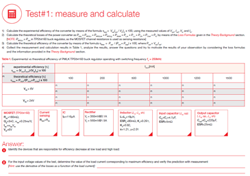
The exercise is to measure input and output power with varying load, for an input voltage of 6 and 24 volt and calculate efficiency.

Then you have to compare that with the efficiency calculation. You get enough help in the doc to get that calculated.

Simulation affectionados (yes you Jon) may want to run it through Spice or the likes.


Then follow the steps to set everything up and perform the exercise (click to enlarge).


imageimage


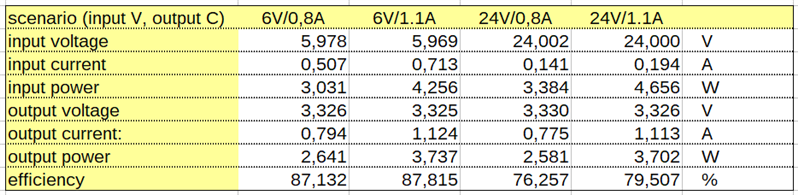
You record both calculated and measured values in a table, for those efficiency and loss tests.


imageimage
imageimage


Here's a few of my measurement recordings and some scope captures:

image


  • Input 6 Output current 0.8 A

image


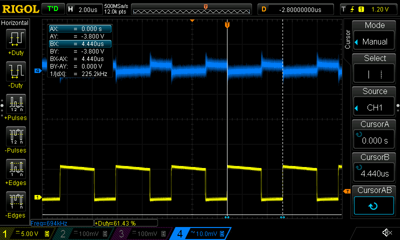
  • Input 24V Output current 0.8 A

image

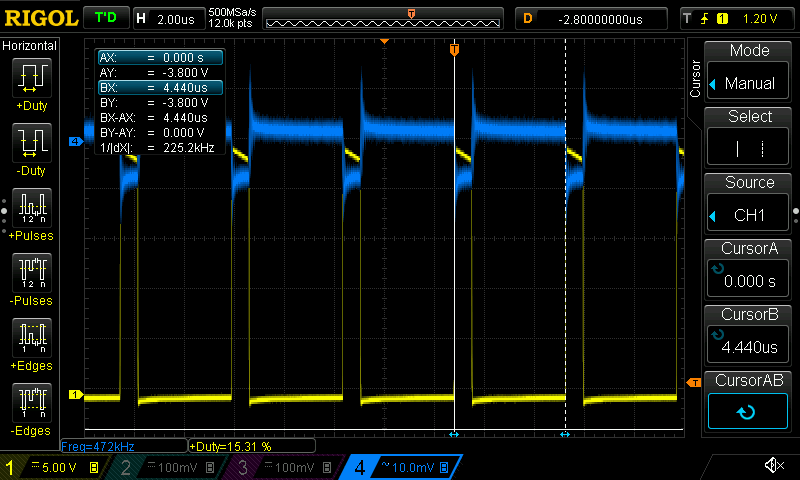
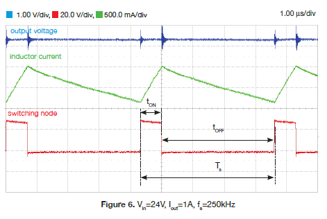
Here's what the manual shows for 24V 1A. It's obvious that my current measurement method (blue in the capure above vs. green in the TI manual) is not up to the game.

image

What I haven't done yet is to measure the behaviour when the regulator operates in non-continuous mode.

image

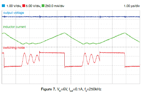
That's a todo for the next article. I'll also comment on educational value and vendor lock-in score of the kit (spoiler: high and low image)


Related Blog
1a: 1st Experiment Set-up
1b: 1st Experiment Lab Setup
1c: 1st Experiment Measure
2: Educational Value

Road Test: TI-PMLK Buck Experiment Board: TPS54160 & LM3475

  • Sign in to reply

Top Comments

  • Jan Cumps
    Jan Cumps over 8 years ago in reply to jc2048 +2
    i think not having the DC component is ok in this case, where I'm trying to visualise current (edit: current waveform) and ripple trough the inductor. If I have some time next week-end, I'll try to put…
  • Jan Cumps
    Jan Cumps over 8 years ago in reply to jc2048 +2
    This is the best signal I can snoop with my naive air coil tap: The yellow line is the voltage inducted into the coil I wound over the current shunt, amplified by a µCurrent in nA mode. I'm misusing the…
  • jc2048
    jc2048 over 8 years ago +1
    It's obvious that my current measurement method (blue in the capure above vs. green in the TI manual) is not up to the game. I don't know - it's quite good for something that you've improvised. But you…
Parents
  • jc2048
    jc2048 over 8 years ago

    It's obvious that my current measurement method (blue in the capure above vs. green in the TI manual) is not up to the game.

    I don't know - it's quite good for something that you've improvised. But you have your blue trace upside down [just swap the secondary coil ends]. Then, if you integrate the waveform, you get back to the primary current. (The induced voltage is proportional to the rate of change of the current in the sense resistor.)


    The biggest problem with what you are doing is that you lose the dc component - you see the ripple, but not the dc offset from zero [which isn't very good if you're trying to learn the fundamentals of dc-dc converters].


    The 20A/50MHz probe they recommend would work in a similar way - integrating the output of a coil for the high-frequency part. Difference is that it would also have some way to do the dc and low-frequency part (a hall-effect sensor). 

    • Cancel
    • Vote Up +1 Vote Down
    • Sign in to reply
    • More
    • Cancel
  • Jan Cumps
    Jan Cumps over 8 years ago in reply to jc2048

    This is the best signal I can snoop with my naive air coil tap:


    image


    The yellow line is the voltage inducted into the coil I wound over the current shunt,

    amplified by a µCurrent in nA mode.


    I'm misusing the µCurrent as sensitive voltage amplifier here.

    It has enough bandwidth. The witching freq is 225 kHz and the -3dB of the µCurrent is above 300 kHz.


    image


    I will likely get better results if I use a ferrite kernel and only a few windings farther apart.

    I have no cheapo solution to include the DC component of the current.

    • Cancel
    • Vote Up +2 Vote Down
    • Sign in to reply
    • More
    • Cancel
Comment
  • Jan Cumps
    Jan Cumps over 8 years ago in reply to jc2048

    This is the best signal I can snoop with my naive air coil tap:


    image


    The yellow line is the voltage inducted into the coil I wound over the current shunt,

    amplified by a µCurrent in nA mode.


    I'm misusing the µCurrent as sensitive voltage amplifier here.

    It has enough bandwidth. The witching freq is 225 kHz and the -3dB of the µCurrent is above 300 kHz.


    image


    I will likely get better results if I use a ferrite kernel and only a few windings farther apart.

    I have no cheapo solution to include the DC component of the current.

    • Cancel
    • Vote Up +2 Vote Down
    • Sign in to reply
    • More
    • Cancel
Children
  • jc2048
    jc2048 over 8 years ago in reply to Jan Cumps

    It has enough bandwidth. The switching freq is 225 kHz and the -3dB of the µCurrent is above 300 kHz.

    Don't let MK catch you saying things like that. If the waveform were a sinewave, you could say the amplifier had enough bandwidth. As it is, the amplifier is low-pass filtering the waveform and giving you the fundamental 225kHz plus some of the lower harmonics heavily attenuated by the roll-off of the amplifier above 300kHz.

    • Cancel
    • Vote Up +1 Vote Down
    • Sign in to reply
    • More
    • Cancel
  • jc2048
    jc2048 over 8 years ago in reply to Jan Cumps

    I have no cheapo solution to include the DC component of the current.

    If you don't mind building circuits, the most straightforward way to measure the current would be the same way that the chip does - just amplify the voltage across the sense resistor. That gets you both the ac and dc components. The ac performance of a resistor is pretty good - the limiting factor will probably be the amplifier bandwidth.


    You could build yourself a simple differential probe out of op-amps for the oscilloscope. You'd need to take care over offset voltages and choose a reasonable GBW for the op-amps, depending on how much gain you need. The input impedance doesn't need to be particularly high when you're measuring a 10mOhm circuit - 1k looks like a high impedance to 10mOhm, and keeping it low will help reduce noise pick-up - and you don't really need proper scope probes, just short wires with small clips that you can attach to the sense resistor leads. [If you were actually interested in doing this, ask MK for some informed advice on what parts to use and the possible pitfalls. He's done so much of this kind of thing he can probably sit there and predict ahead of time the problems you'd have with it.]

    • Cancel
    • Vote Up 0 Vote Down
    • Sign in to reply
    • More
    • Cancel
  • Jan Cumps
    Jan Cumps over 8 years ago in reply to jc2048

    Jon Clift wrote:


    It has enough bandwidth. The switching freq is 225 kHz and the -3dB of the µCurrent is above 300 kHz.

    Don't let MK catch you saying things like that. If the waveform were a sinewave, you could say the amplifier had enough bandwidth. As it is, the amplifier is low-pass filtering the waveform and giving you the fundamental 225kHz plus some of the lower harmonics heavily attenuated by the roll-off of the amplifier above 300kHz.

    True - and you can see it on the image (rolled off and cleaner because the µCurrent also filters out the high-frequency noise component).

    Linear on the non-amplified capture, with the high frequency noise (I will check if I can low-pass the signal on my scope. I've only found a 20 MHz setting, maybe there's a digital filter option somewhere....)

    • Cancel
    • Vote Up +1 Vote Down
    • Sign in to reply
    • More
    • Cancel
  • Jan Cumps
    Jan Cumps over 8 years ago in reply to Jan Cumps

    jancumps wrote:

    ...

    (I will check if I can low-pass the signal on my scope. I've only found a 20 MHz setting, maybe there's a digital filter option somewhere....)


    Ah there is one, in the math menu, lowpass, highpass, bandpass, and bandstop. Way down in the math options.

    I'll set up my test circuit again and see if I can come up with a cleaner result....

    • Cancel
    • Vote Up +1 Vote Down
    • Sign in to reply
    • More
    • Cancel
element14 Community

element14 is the first online community specifically for engineers. Connect with your peers and get expert answers to your questions.

  • Members
  • Learn
  • Technologies
  • Challenges & Projects
  • Products
  • Store
  • About Us
  • Feedback & Support
  • FAQs
  • Terms of Use
  • Privacy Policy
  • Legal and Copyright Notices
  • Sitemap
  • Cookies

An Avnet Company © 2025 Premier Farnell Limited. All Rights Reserved.

Premier Farnell Ltd, registered in England and Wales (no 00876412), registered office: Farnell House, Forge Lane, Leeds LS12 2NE.

ICP 备案号 10220084.

Follow element14

  • X
  • Facebook
  • linkedin
  • YouTube