element14 Community
element14 Community
    Register Log In
  • Site
  • Search
  • Log In Register
  • Community Hub
    Community Hub
    • What's New on element14
    • Feedback and Support
    • Benefits of Membership
    • Personal Blogs
    • Members Area
    • Achievement Levels
  • Learn
    Learn
    • Ask an Expert
    • eBooks
    • element14 presents
    • Learning Center
    • Tech Spotlight
    • STEM Academy
    • Webinars, Training and Events
    • Learning Groups
  • Technologies
    Technologies
    • 3D Printing
    • FPGA
    • Industrial Automation
    • Internet of Things
    • Power & Energy
    • Sensors
    • Technology Groups
  • Challenges & Projects
    Challenges & Projects
    • Design Challenges
    • element14 presents Projects
    • Project14
    • Arduino Projects
    • Raspberry Pi Projects
    • Project Groups
  • Products
    Products
    • Arduino
    • Avnet & Tria Boards Community
    • Dev Tools
    • Manufacturers
    • Multicomp Pro
    • Product Groups
    • Raspberry Pi
    • RoadTests & Reviews
  • About Us
  • Store
    Store
    • Visit Your Store
    • Choose another store...
      • Europe
      •  Austria (German)
      •  Belgium (Dutch, French)
      •  Bulgaria (Bulgarian)
      •  Czech Republic (Czech)
      •  Denmark (Danish)
      •  Estonia (Estonian)
      •  Finland (Finnish)
      •  France (French)
      •  Germany (German)
      •  Hungary (Hungarian)
      •  Ireland
      •  Israel
      •  Italy (Italian)
      •  Latvia (Latvian)
      •  
      •  Lithuania (Lithuanian)
      •  Netherlands (Dutch)
      •  Norway (Norwegian)
      •  Poland (Polish)
      •  Portugal (Portuguese)
      •  Romania (Romanian)
      •  Russia (Russian)
      •  Slovakia (Slovak)
      •  Slovenia (Slovenian)
      •  Spain (Spanish)
      •  Sweden (Swedish)
      •  Switzerland(German, French)
      •  Turkey (Turkish)
      •  United Kingdom
      • Asia Pacific
      •  Australia
      •  China
      •  Hong Kong
      •  India
      • Japan
      •  Korea (Korean)
      •  Malaysia
      •  New Zealand
      •  Philippines
      •  Singapore
      •  Taiwan
      •  Thailand (Thai)
      • Vietnam
      • Americas
      •  Brazil (Portuguese)
      •  Canada
      •  Mexico (Spanish)
      •  United States
      Can't find the country/region you're looking for? Visit our export site or find a local distributor.
  • Translate
  • Profile
  • Settings
STEM Projects
  • Learn
  • Learning Center
  • STEM Academy
  • STEM Projects
  • More
  • Cancel
STEM Projects
Blog The Rise of the Raspberry Pi "Turtle Bot"
  • Blog
  • Forum
  • Documents
  • Events
  • Polls
  • Files
  • Members
  • Mentions
  • Sub-Groups
  • Tags
  • More
  • Cancel
  • New
Join STEM Projects to participate - click to join for free!
  • Share
  • More
  • Cancel
Group Actions
  • Group RSS
  • More
  • Cancel
Engagement
  • Author Author: kitfud
  • Date Created: 22 Dec 2014 5:43 AM Date Created
  • Views 1677 views
  • Likes 6 likes
  • Comments 11 comments
  • raspberry pi educators design challenge
  • robot
  • raspberry_pi_educator
  • pi educators sub space
  • raspberrypi_education
  • turtle bot
Related
Recommended

The Rise of the Raspberry Pi "Turtle Bot"

kitfud
kitfud
22 Dec 2014

    In my last blog I explained how I am using the Python library (which is pre-installed on a Raspberry Pi) to teach programming. It's convenient, and "pretty cool" when it's projected onto a large whiteboard in my office; but this isn't the end all to what I hope to achieve with the Raspberry Pi B+...image


Now that it's the Christmas holidays I've had plenty of time to work on my robotics stuff as a hobby. Below is my "Fat Cat" robot made of a Dagu 5 robot chassis, a Raspberry Pi B+ an Arduino Mega along with the lovely Pi Camera board:


image

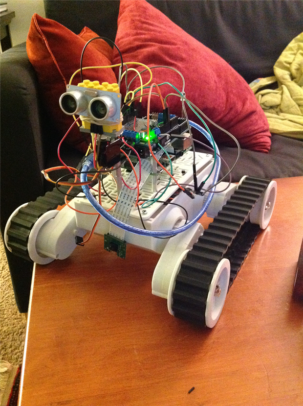
I call it the "Fat Cat" because I think my cat thinks it's a living entity. Moreover, she is much smaller than this mash-up of electronics. Anyway, this Fat Cat is the culmination of what I have been able to achieve thus far in my robotics career. Let me ruminate on the past by presenting my obstacle avoiding "Dragon Bot".....

You don't have permission to edit metadata of this video.
Edit media
x
image
Upload Preview
image


Oh what good times! The video's artistic flair may take away from the seriousness of the obstacle avoiding genius. The problem with this type of contraption though, is that you can't just yell at it to stop like a golden retriever in your favorite park. No! Instead you have to chase it all over the floor, pick it up and then turn it off manually which is an inconvenience when you think about how we are living in the year 2014; the year of the internet and ultra high def TVs...yada...yada...yada....


Anyway, I eventually invested in an Arduino Yun, a wifi version of a regular Arduino in an attempt to gain remote control over my aimless obstacle avoiding Dragon Bot! Below is a picture of an Arduino Yun which, like the Raspberry Pi, has a LINUX processor embedded  onboard:


image

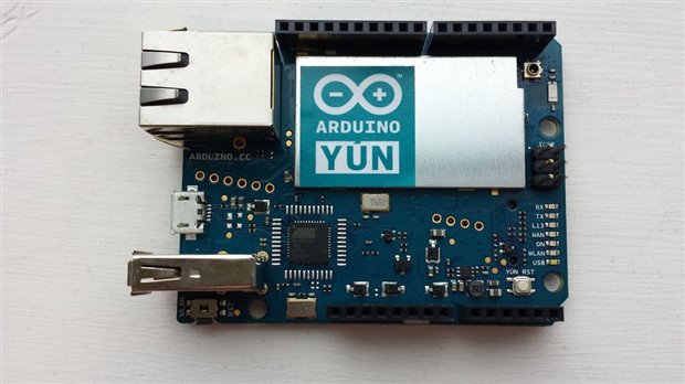
It is quite a snazzy little micro-controller but the way I'd drive my updated Dragon Bot was through entering commands in the Yun's version of the serial monitor called Console. It can't be called a Serial Communication because it is not actually attached to a computer but living in the nether world of wifi image.


By entering in letters and sending them through the Arduino Console I could drive my robot around and then with the sending of a key stroke I could set the robot into obstacle avoiding "autopilot" mode. Then bring it back under my control (like a little zombie) through another keystroke. However, because I was using Console  I could not use Python and the Pyserial library to create a graphical control interfaceimage. This is an Arduino bummer, and is why the Raspberry Pi came into play when I developed the "Fat Cat." But I must get back to the point, and not let my ramblings about the Fat Cat detract.


This blog post is about the Turtle Bot, how I developed it and how it will be used when the school year picks up again to teach Python programming. In this way, the Turtle Bot is a pedagogical tool.


Below is a picture of the "Fat Cat" with the completed "Turtle Bot." Notice the differences in size between them:

image


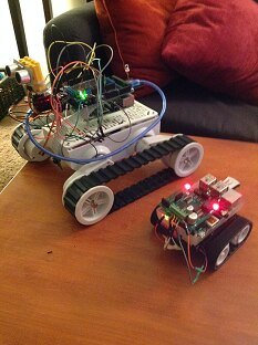
The smaller "Turtle Bot" is built off of a Pololu Zumo Bot Chassis; a relatively cheap base and very simple to work with. On top of it is the Raspberry Pi B+ along with a Raspibot V2 Motorcontroller set over the GPIO pins. Now, you not need to use a Raspirobot Board V2 to construct this; for me it was just convenient and at my disposal to use this attachable motor controller built specifically for the Raspberry Pi:


image

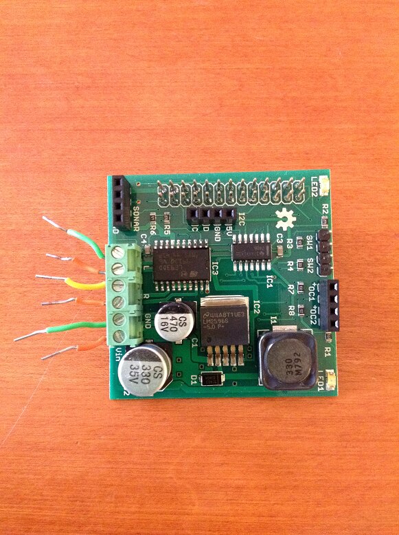
What's nice about this add on board is that it comes with a pre written Python library which includes commands that can be easily modified into a python script to control forward, backward, left and right movements. Click the link HERE to learn more.


However, when I first starting thinking about making a robot out of the raspberry Pi I watched this video and it turns out that any H Bridge motor controller will work for making Raspberry Pi robots. Note: you need to use a motor controller because otherwise you'll burn out the GPIO pins on the Raspberry Pi and also you won't be able to achieve bi-directional motor movement:

You don't have permission to edit metadata of this video.
Edit media
x
image
Upload Preview
image


The guy who makes these films is very knowledgeable and I plan to do the exercise he runs at the end of the film where the Zumo robot draws shapes out of a Python script with my students (refer to 12:10 in the video above). In general, it's the types of activities which bring programming and robotics into an experience that you can touch and feel. So far, I think that one of the constraints of teaching programming for beginners is that oftentimes lessons are constrained to the surfaces of a computer screen. Why not have feedback from code jump out at you like a Zumo Robot constructing the latest and greatest octagon on paper!image


Anyway, have I mentioned that I ended up producing my own robot using the Zumo chassis and my swag motor controller image? Here it is!

The mighty... "Turtle Bot!"

image

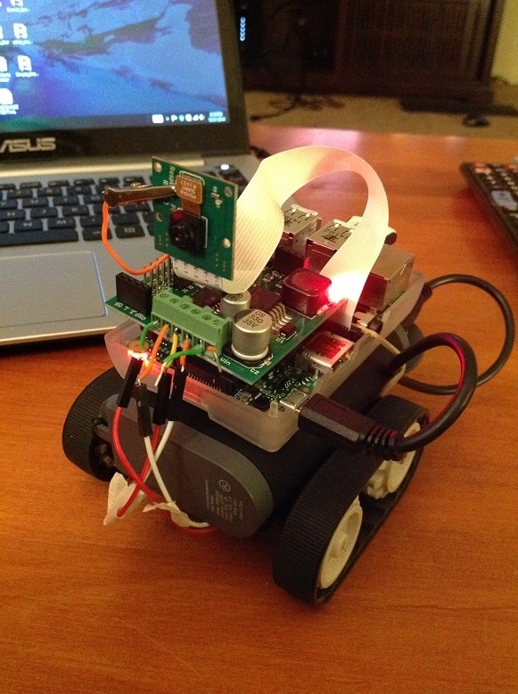
Notice how I have placed the Pi Camera on board to give me a Turtle's Eye View of the terrain. Ultimately, this adds to the awe of driving the turtle bot and also helps the driver fall into the "mindset" of the turtle. How else would this be possible without seeing the world through it's lowly HD video eyes?


If you're wondering why I keep calling this thing the Turtle Bot, it is because I plan to incorporate this educational tool into my next programming lessons with William. We have gone over drawing geometric forms in Python using the Turtle library. We have been declaring t = turtle.Pen() but now that we have this thing it might as well be "Turtle_Bot" = turtle.Pen(). I am hoping to attach a pen to the back of the vehicle so it can literally become a remote pen which drives around to trace shapes. How cool and valuable of a learning experience would that be; suddenly bringing the virtual 2D world of Python turtle into the domain of real life; now actualized with the "Turtle Bot!"


Additionally, I am hoping to relate the lesson on drawing shapes using a turtle to the development of buttons and graphical interfaces using the Tkinter library in Python. Here is a great tutorial article I found online as to how to create and control your robots using graphical interfaces made in Python - CLICK HERE


Below is the graphical interface I adapted from the article to control the "Fat Cat" which I then reused and adapted again to control the Turtle Bot:

image

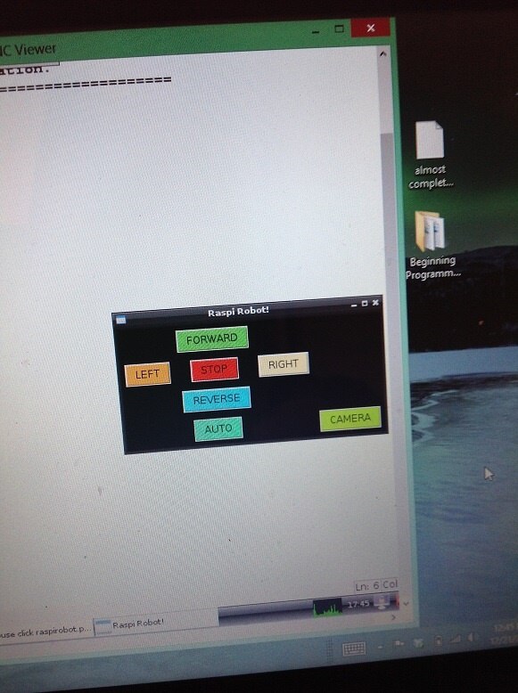
Nothing fancy, but what's neat is that my computer has a touch screen so I can tap each of those buttons to control the bot! Constructing a unique control interface for the Turtle Bot in Python will be another activity I'll run with my programming students. You'll notice too that I have a CAMERA button, when that is clicked it will take me to a live online stream of the Pi Camera board. I did a lot of research into how to do this, as streaming live video from the perspective of a robot is something I've wanted to complete since the summer and finally, with the Raspberry Pi it is unbelievable easy. The link on how to do this with the RPi CAM Control is HERE


Basically, it streams video to a weblink which is the IP address of your Pi computer. This can be accessed by any external computer on the wireless network so don't go and do something silly like ride the Turtle Bot around in a public cafe. You may unexpectedly find that every other patron knows the eye of the turtle (maybe without your permission)!


The most important step; and also the most important realization I've recently had with the Pi; is being able to control the LINUX interface from another computer. This means that I don't need to plug the Pi in with an HDMI cord to monitor  what's going on inside. This is HUGE if you are thinking about using the Pi as a robotics controller because it's not like you can have a TV screen being dragged on the back of a teeny weeny robot.


Enter VNC viewer! The APP which allows you to broadcast another computer's screen remotely to your own in a window. Here is a picture which may explain what I mean:

image

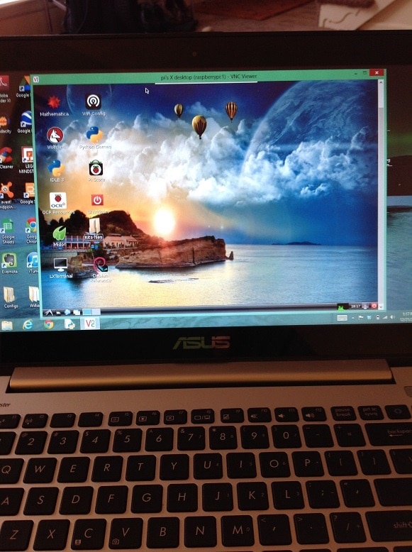
With the VNC viewer I now have my Raspberry Pi desktop mirrored onto my laptop computer's desktop. Windows within windows which becomes a feast for the eyes and also a thrill to the robot enthusiast. Controlling a Raspberry Pi is much more convenient and user friendly this way and I highly recommend it. The other alternative is to SSH into your Raspberry Pi via PuTTY (if you have a PC) but we won't get into that. Instead, refer to this link to set up your Raspberry Pi for tight VNC viewer:


This is the single most important thing I learned while completing the Turtle Bot project; it is that the VNC viewer is essential and very useful for those creating robots and maybe for those in schools who do not have an abundance of desktop monitors or TVs with HDMI ports.


In the end, VNC viewer, a TKinter control interface and the RPi live feed allowed me to set up my laptop desktop screen like this once I re-sized the windows image:

image

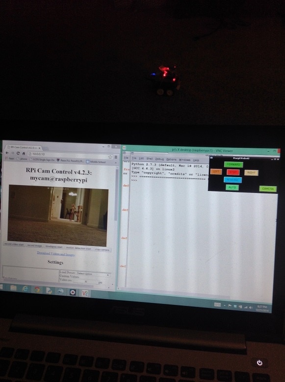
Note: that is the robot sitting in the darkness behind the computer screen. In conclusion, I will use the Turtle Bot as the foundation for building upon my first lesson in Python programming. Students will:


1. Will learn how to program the Turtle Bot to drive in geometric patters; similar to the ways in which the turtle moves around on the Python/IDLE interface

2. Learn how to program their own graphical interface for remote control of the Turtle Bot using Python's TKinter library

3. Use the on-board pi board camera to do exploratory missions; for example, movement to a location and then take a picture


The third objective completes my educational philosophy where I try and situate lessons within the context of a greater theme; in this case, it is about a mission to reach a location and document footage. Much like a rover travels to Mars, drives around and then returns back to earth with footage. Perhaps this is a method for encouraging young students to become astronauts. More importantly, I know that this will be a method for driving intellectual curiosity into the possibilities for combining technology at our disposal.


The video below shows the Turtle Bot, freshly minted, moving around my living room floor......

You don't have permission to edit metadata of this video.
Edit media
x
image
Upload Preview
image

  • Sign in to reply

Top Comments

  • mcb1
    mcb1 over 10 years ago +1
    Nice idea. I have one of those chassis, and the use of the camera is a good addition. Thanks for sharing Mark
Parents
  • mcb1
    mcb1 over 10 years ago

    Nice idea.

    I have one of those chassis, and the use of the camera is a good addition.


    Thanks for sharing

    Mark

    • Cancel
    • Vote Up +1 Vote Down
    • Sign in to reply
    • More
    • Cancel
  • kitfud
    kitfud over 10 years ago in reply to mcb1

    Thanks for the positive feedback image! The Zumo chassis are great but in other projects with them I've had trouble with them veering off to the left when I try and drive strait. From reading about the problem online this is due to a lack of wheel encoders which can measure and compare the exact rotation/speeds between motors. For the purposes of the Turtle Bot through, I don't think it will matter all that much because the shapes I hope my students will draw are going to be basic and aren't going to be in an art gallery, I'm sure. Kind Regards and let me know if you have any ideas to expand this project further,

    Kit

    • Cancel
    • Vote Up 0 Vote Down
    • Sign in to reply
    • More
    • Cancel
  • kitfud
    kitfud over 10 years ago in reply to Problemchild

    Is this similar to what you are suggesting:

    You don't have permission to edit metadata of this video.
    Edit media
    x
    image
    Upload Preview
    image


    vs.


    You don't have permission to edit metadata of this video.
    Edit media
    x
    image
    Upload Preview
    image


    He seems to have calibrated his Zumo robot with encoders but I need to know how to write the code to apply the data an encoder sends back to an Adafruit motor shield (so this is in Arduino sudo C), but I do have it linked up to a Raspberry Pi so it can communicate through Pyserial and the data can be processed and then acted on in Python. Any help developing code to control power output to motors in this way (Python and/or Arduino "C") would be much appreciated!

    • Cancel
    • Vote Up 0 Vote Down
    • Sign in to reply
    • More
    • Cancel
  • mcb1
    mcb1 over 10 years ago in reply to kitfud

    Kit


    For mine I simply had a variable for calibration (0.95 from memory for one of them)

    The motor speed PWM simply had this applied to it after all the other bits (speed and turn amount).

    In reverse it was removed, but you could apply one for reverse.


    You need to include YOUR code so we aren't guessing.

    I'm assumming you DON'T have encoders.


    You can attach it in zip file, or for the Arduino cut and paste using the >> and Syntax Highlighting  C++ which gives something like this


    Use
    >>
    then
    select
    Syntax Highlighting
    C++


    Mark

    • Cancel
    • Vote Up 0 Vote Down
    • Sign in to reply
    • More
    • Cancel
  • kitfud
    kitfud over 10 years ago in reply to mcb1

    I do have encoders on my Dagu 5 robot chassis (The Fat Cat! from my Blog!!) and this is where I am trying to understand how to use them. This is unrelated to the Zumo bot that I hope to use with my students. However, here is the code I used cut down to just a forward movement using encoders and a motor shield. In my example I've allowed speed "i" to float up to 105 for an upward calibration relative to the serial output of right and left velocity. Thank you for your help by the way:

    #include <Wire.h>
    #include <Adafruit_MotorShield.h>
    #include <Encoder.h>


    // Create the motor shield object with the default I2C address
    Adafruit_MotorShield AFMS = Adafruit_MotorShield(); 
    // Or, create it with a different I2C address (say for stacking)
    // Adafruit_MotorShield AFMS = Adafruit_MotorShield(0x61); 
    
    
    // And connect a DC motor to port M1
    Adafruit_DCMotor *myMotor = AFMS.getMotor(1);
    Adafruit_DCMotor *myMotor2 = AFMS.getMotor(2);
    
    
    #define RightEncoderPinA 4
    #define RightEncoderPinB 2
    #define LeftEncoderPinA  3
    #define LeftEncoderPinB  6
    
    // Loop time for calculating velocity
    #define DELAY_TIME 10 // In ms
    
    // Define physical constants of the wheel for wheel encoding
    #define WHEEL_CIRCUMFERENCE 0.239 // In meters
    #define WHEEL_TICKS 332          // The number of 'ticks' for a full wheel cycle
    #define WHEEL_DIST .1985           // The distance between wheels in meters
    
    // Variables for storing the calculated velocity
    double leftvelocity;
    double rightvelocity;
    
    // Variables for storing position info
    long OldLPos;
    long NewLPos;
    long OldRPos;
    long NewRPos;
    
    // Volatile variables that can be changed inside of interrupt functions
    volatile unsigned int RightEncoderPos = 0;
    volatile unsigned int LeftEncoderPos = 0;
    double LdVal = 0;
    double RdVal = 0;
    
    
    void setup() {
      // initialize serial communication:
      Serial.begin(9600);
      // initialize the LED pin as an output:
    
    
      AFMS.begin();  // create with the default frequency 1.6KHz
      //AFMS.begin(1000);  // OR with a different frequency, say 1KHz
      
      myMotor->setSpeed(100);
      myMotor2->setSpeed(100);
    
       
      pinMode(LeftEncoderPinA, INPUT);
      pinMode(LeftEncoderPinB, INPUT);
      pinMode(RightEncoderPinA, INPUT);
      pinMode(RightEncoderPinB, INPUT);
    
      attachInterrupt(0, RightEncoderEvent, CHANGE);
      attachInterrupt(1, LeftEncoderEvent, CHANGE);
    
    } 
       
    void forward ()
    {
      uint8_t i;
      myMotor->run(FORWARD);
      myMotor2->run(FORWARD); 
      }


    void loop() {
      uint8_t i;
      
     // Calculate current speeds
      GetSpeeds();
    
      // Print velocity (m/s) to serial line
      Serial.print("Left Velocity: ");
      PrintDouble(leftvelocity, 4);
    
      Serial.print("Right Velocity: ");
      PrintDouble(rightvelocity, 4);
      
      delay(600);//rate at which info is printed from the encoders
      //i is within 105 because I am giving room for an upward calibration for one of the motors
      
      if (leftvelocity > rightvelocity){
       for (i=100; i<105; i++) {
        myMotor->setSpeed(i);  
        delay(10);
       }
      }
        
      if (leftvelocity < rightvelocity){
       for (i=100; i<105; i++) {
       myMotor2->setSpeed(i);  
       delay(10);
       }
      }
       
       if (leftvelocity == rightvelocity){
       myMotor->setSpeed(i);
       myMotor2->setSpeed(i);  
       delay(10);
      }
       }


    // Return the real-world vehicle speed
    void GetSpeeds()
    {
      // Find the old and new encoder positions
      OldLPos = LeftEncoderPos;
            OldRPos = RightEncoderPos;
      delay(DELAY_TIME);
      NewLPos = LeftEncoderPos;
            NewRPos = RightEncoderPos;
    
      // If an integer overflow occures, throw out the new value
      if(abs(NewLPos - OldLPos) < 60000)
      LdVal = ((double)(NewLPos - OldLPos) / (double)DELAY_TIME) * 1000.0;
            if(abs(NewRPos - OldRPos) < 60000)
      RdVal = ((double)(NewRPos - OldRPos) / (double)DELAY_TIME) * 1000.0;
    
      // Convert between angular velocity to velocity
      double LangVel = LdVal / (double)WHEEL_TICKS;
      leftvelocity = (LangVel * WHEEL_CIRCUMFERENCE);
    
            double RangVel = RdVal / (double)WHEEL_TICKS;
      rightvelocity = (RangVel * WHEEL_CIRCUMFERENCE);
    }
    
    
    // Encoder event for the interrupt call
    void LeftEncoderEvent()
    {
      // Read for data and bit changes
      // This is gray-code logic
      if (digitalRead(LeftEncoderPinA) == HIGH)
      {
        if (digitalRead(LeftEncoderPinB) == LOW)
          LeftEncoderPos++;
        else
          LeftEncoderPos--;
      }
      else
      { 
        if (digitalRead(LeftEncoderPinB) == LOW)
          LeftEncoderPos--;
        else
          LeftEncoderPos++;
      }
    }
    
    void RightEncoderEvent()
    {
      // Read for data and bit changes
      // This is gray-code logic
      if (digitalRead(RightEncoderPinA) == HIGH)
      {
        if (digitalRead(RightEncoderPinB) == LOW)
          RightEncoderPos++;
        else
          RightEncoderPos--;
      }
      else
      { 
        if (digitalRead(RightEncoderPinB) == LOW)
          RightEncoderPos--;
        else
          RightEncoderPos++;
      }
    }
    
    // Print a double value onto the serial stream
    // This is from the Arduino.cc forum
    void PrintDouble( double val, byte precision)
    {
      Serial.print (int(val));  //prints the int part
      if( precision > 0) {
        Serial.print("."); // print the decimal point
        unsigned long frac;
        unsigned long mult = 1;
        byte padding = precision -1;
        while(precision--)
      mult *=10;
    
        if(val >= 0)
      frac = (val - int(val)) * mult;
        else
      frac = (int(val)- val ) * mult;
        unsigned long frac1 = frac;
        while( frac1 /= 10 )
      padding--;
        while(  padding--)
      Serial.print("0");
        Serial.println(frac,DEC) ;
      }
    }


    I have a feeling that this all has something to do with how I am understanding "i" as a constant which I have taken from the Adafruit basic motor shield example in which a motor accelerates forward and then decelerates backwards:


    /* 
    This is a test sketch for the Adafruit assembled Motor Shield for Arduino v2
    It won't work with v1.x motor shields! Only for the v2's with built in PWM
    control
    
    
    For use with the Adafruit Motor Shield v2 
    ----> http://www.adafruit.com/products/1438
    */
    
    
    #include <Wire.h>
    #include <Adafruit_MotorShield.h>
    #include "utility/Adafruit_PWMServoDriver.h"
    
    
    // Create the motor shield object with the default I2C address
    Adafruit_MotorShield AFMS = Adafruit_MotorShield(); 
    // Or, create it with a different I2C address (say for stacking)
    // Adafruit_MotorShield AFMS = Adafruit_MotorShield(0x61); 
    
    
    // Select which 'port' M1, M2, M3 or M4. In this case, M1
    Adafruit_DCMotor *myMotor = AFMS.getMotor(1);
    // You can also make another motor on port M2
    //Adafruit_DCMotor *myOtherMotor = AFMS.getMotor(2);
    
    
    void setup() {
      Serial.begin(9600);           // set up Serial library at 9600 bps
      Serial.println("Adafruit Motorshield v2 - DC Motor test!");
    
    
      AFMS.begin();  // create with the default frequency 1.6KHz
      //AFMS.begin(1000);  // OR with a different frequency, say 1KHz
      
      // Set the speed to start, from 0 (off) to 255 (max speed)
      myMotor->setSpeed(150);
      myMotor->run(FORWARD);
      // turn on motor
      myMotor->run(RELEASE);
    }
    
    
    void loop() {
     (
      
      Serial.print("tick");
    
    
      myMotor->run(FORWARD);
      for (i=0; i<255; i++) {
        myMotor->setSpeed(i);  
        delay(10);
      }
      for (i=255; i!=0; i--) {
        myMotor->setSpeed(i);  
        delay(10);
      }
      
      Serial.print("tock");
    
    
      myMotor->run(BACKWARD);
      for (i=0; i<255; i++) {
        myMotor->setSpeed(i);  
        delay(10);
      }
      for (i=255; i!=0; i--) {
        myMotor->setSpeed(i);  
        delay(10);
      }
    
    
      Serial.print("tech");
      myMotor->run(RELEASE);
      delay(1000);
    }


    Your help is much appreciated in understanding how to structure my code. Basically I'm trying to accelerate one wheel to catch up with the other as a form of calibration. I could easily decelerate the faster wheel to meet the acceleration of the faster one as well but this didn't work out well when I tried it out a while ago (I deleted that example because it was a mess). image

    • Cancel
    • Vote Up 0 Vote Down
    • Sign in to reply
    • More
    • Cancel
  • mcb1
    mcb1 over 10 years ago in reply to kitfud

    Kit

    I was thinking it was your Zumo without encoders that we were dealing with.


    Regardless .... my way of looking at it, is you can't make a motor go faster than the top speed, so therefore you need to slow down the 'physically' faster motor.

    Unless you do a calibration at all settings (possible), we can assume it will be constant (ie always 1 or 2 % faster), and therefore when travelling forward its always applied, regardless of the speed/pwm setting.


    In reverse you can always change, or not bother, since you are only reversing to get out of trouble, which involves a turn afterwards (or its a reversing turn).


    Adafruit example

    The Adafruit example simply speeds up the motor (0 to 255) and slows it down (255 to 0) using i as the variable.

    The statement myMotor->setSpeed(i) could be translated to  myMotor->setSpeed(0) through to myMotor->setSpeed(255) with an increase every 10mS (delay(10).


    Yours

    You set the speed with 

    myMotor->setSpeed(100); 
    myMotor2->setSpeed(100);


    then do some checks on the velocity and decide if one is faster.

    if (leftvelocity > rightvelocity){  
    for (i=100; i<105; i++) {  
        myMotor->setSpeed(i);    
        delay(10);  
       }

    However this will always make the speed increase from the 100 to 105 at a 10mS rate.

    so now the settings are

    myMotor->setSpeed(105);
    myMotor2->setSpeed(100);

    If the BOT is turning right then the left velocity will be higher.


    The problem then changes when you discover the right is faster

    if (leftvelocity < rightvelocity){  
    for (i=100; i<105; i++) {  
       myMotor2->setSpeed(i);    
       delay(10);  
       }

    Remember that myMotor is 105

    You do the same thing and ramp myMotor2 up to 105 as well.

    myMotor->setSpeed(105);
    myMotor2->setSpeed(105);


    OR if they are the same

    if (leftvelocity == rightvelocity){  
       myMotor->setSpeed(i);  
       myMotor2->setSpeed(i);    
       delay(10);

    Because i is still 105 from the last adjustment, you set both at 105.

    myMotor->setSpeed(105);
    myMotor2->setSpeed(105);


    Also you may wish to remove the delay(600) at line 94 above.

    You can replace it with a timer based on MIllis() where you check to see if 600mS has passed since the last update.

    (See the BlinkWithoutDelay example)


    I use the analogy of filling a swimming pool.

    Delay is standing there holding the hose ... you can't do anything else (except an interrrupt)

    Using Millis() is liie coming back at regular intervals ... is it full yet.


    Mark

    • Cancel
    • Vote Up 0 Vote Down
    • Sign in to reply
    • More
    • Cancel
  • kitfud
    kitfud over 10 years ago in reply to mcb1

    Thanks for the quick reply and working through my code. What do I need to do if the motors adjust so that the necessary strait path is for example:

    myMotor->setSpeed(103)
    myMotor->setSpeed(100)


    Lets say that this is the correct calibration for going strait; how do I fix the motors at this point as the robot is moving dynamically? This is because the strait path is relative to velocity right and velocity left in the serial monitor read off of the encoders not the Motor shield output of for example (105, 100 or the top speed 255). Hopefully I'm phrasing this in an understandable way...because depending on the surface the motors encoders would give different readings for velocity left and velocity right- the robot would hopefully then adapt to maintain the strait course of "forward"....

    • Cancel
    • Vote Up 0 Vote Down
    • Sign in to reply
    • More
    • Cancel
Comment
  • kitfud
    kitfud over 10 years ago in reply to mcb1

    Thanks for the quick reply and working through my code. What do I need to do if the motors adjust so that the necessary strait path is for example:

    myMotor->setSpeed(103)
    myMotor->setSpeed(100)


    Lets say that this is the correct calibration for going strait; how do I fix the motors at this point as the robot is moving dynamically? This is because the strait path is relative to velocity right and velocity left in the serial monitor read off of the encoders not the Motor shield output of for example (105, 100 or the top speed 255). Hopefully I'm phrasing this in an understandable way...because depending on the surface the motors encoders would give different readings for velocity left and velocity right- the robot would hopefully then adapt to maintain the strait course of "forward"....

    • Cancel
    • Vote Up 0 Vote Down
    • Sign in to reply
    • More
    • Cancel
Children
No Data
element14 Community

element14 is the first online community specifically for engineers. Connect with your peers and get expert answers to your questions.

  • Members
  • Learn
  • Technologies
  • Challenges & Projects
  • Products
  • Store
  • About Us
  • Feedback & Support
  • FAQs
  • Terms of Use
  • Privacy Policy
  • Legal and Copyright Notices
  • Sitemap
  • Cookies

An Avnet Company © 2025 Premier Farnell Limited. All Rights Reserved.

Premier Farnell Ltd, registered in England and Wales (no 00876412), registered office: Farnell House, Forge Lane, Leeds LS12 2NE.

ICP 备案号 10220084.

Follow element14

  • X
  • Facebook
  • linkedin
  • YouTube