I'm having fun experimenting with an ADALM1000. Whilst its spec is nothing like that of a professional SMU, it is an interesting way to explore the world of electronics, though with a certain level of frustration when it gets difficult to do things that, with a real SMU, would be a matter of clicking a few buttons.
For this blog, I thought I'd have a go at measuring the DC gain (beta) of a transistor (used common-emitter) versus the collector current, using the built-in functions rather than by scripting anything. How hard could that be? Actually it turned out to be quite difficult, though some of that might be down to the dunderhead that we've got operating the equipment.
My first attempt was the simple, straightforward approach. Source a current to the base of the transistor (via a 220R resistor, as a little insurance in case the output did anything silly before the current regulation began), and source a voltage to the collector whilst measuring the current on the same pin. Unfortunately, the result left a lot to be desired.

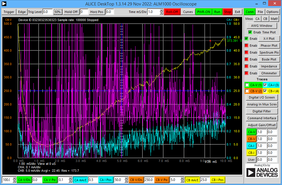
That's supposed to be a nice curve for a 2N3904 transistor, with collector current (in mA) on the X axis, and the gain on the Y axis. We can see better what's going on if I show you the oscilloscope view.

The cyan trace is the base current, the yellow trace is the resulting collector current, and the purple trace is the gain computed with the math function.
It's a mess because of all the noise on the lowish current (<1mA) that's driving the base.
There are a couple of other problems, too. One is that because I'm using a sawtooth waveform, the slew at the start messes up the first part of the curve. A second problem is that, as I don't know the gain ahead of time, I ended up adjusting the range the base current sweeps over to give a reasonable range on the collector current.
So, can I do better? Perhaps I can cobble together something with an op amp.
My next attempt was with this circuit.
This is a form of driven bridge. An output pin (ChA) of the ADALM1000 sinks current through a 47R resistor. The op-amp compares the resulting voltage to that from a 47R dropping the collector current of the transistor and adjusts the transistor base drive to make them match. When the ADALM1000 sweeps the current, the collector current will follow, and it will be less noisy than before because the current is now up in the mA area. The base current I'm measuring with a resistor and the two inputs of the ADALM1000.
That results in this for the curves for a 2N3904 and a BC549C

It's quieter than before, but there's still noise. A disadvantage of doing a differential measurement using two inputs is that it doubles up the noise. A second (hidden) disadvantage is that the ADALM1000 inputs have quite a bit of capacitance (390pF, and whilst the op amp seems to manage, it's not ideal to have that hanging on its output)
Since it was a dual op amp, I decided to instead try a simple differential amplifier with the other half and then I would only need to use one input on the ADALM1000 driven from an op-amp output. Here's the circuit:
That gives me these curves.

It still suffers from the slew in the region up to 4mA, though, whilst it's still not exactly professional level, we're getting a better idea of the shape of the transistor characteristics now. I've thrown in a 2N2222A for good measure.
I wasn't expecting the hump in the curve for the BC549C, so that might indicate a problem of some sort with the test.
Here is the sweep extended up to 100mA:

Keep in mind that they will all be suffering from self-heating at the top end, the 2N3904 and the BC549C in particular where they are above the max dissipation limit. Also, because with my circuit the collector voltage falls with current, I'm not measuring at a constant Vc.
Hope that was of some interest. Although not spectacularly successful, it gives an idea of the kind of things that can be done with the device and a little extra circuitry.
Update 28th July 2023
I've reworked the circuit, to lose the embarrassing high-frequency oscillation (discussed in comments below), by building an integrator around the op amp like this:
Not sure that's the best way to compensate it, but it does seem to give enough extra phase margin at the top end to stop the oscillation and allow the op amp to do its job of mirroring at the transistor collector what is happening at the input.
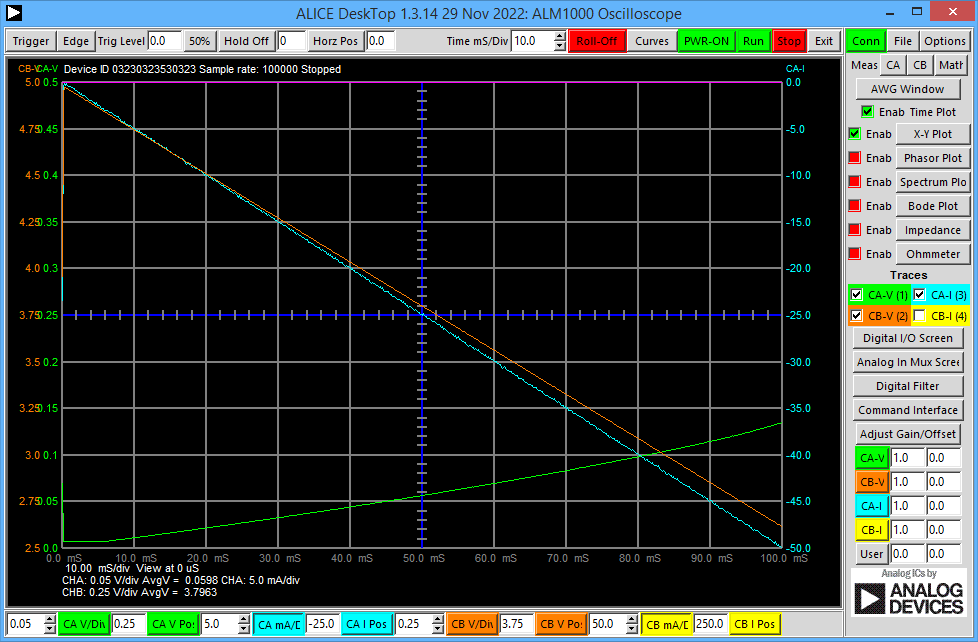
Here are the 'scope view' traces. Now the collector voltage trace (orange) is a straight line as the input sweeps the current [cyan trace]. The green trace is the output of the differential amplifier, where the resulting voltage is proportional to the transistor base current.

That gives this for the plot of transistor gain against collector current.

Leaving aside the mess up to about 5mA, the noise on the current output from the ADALM1000 affecting the calculation of the gain quite badly at lower currents, and the untidy lines from the 'fly-back' at the end, that's not too bad.
Previous blogs
A Short Informal Review of the ADALM1000 from Analog Devices
Experimenting With an All-Pass Filter using the ADALM1000 from Analog Devices

Top Comments
-

BigG
-
Cancel
-
Vote Up
0
Vote Down
-
-
Sign in to reply
-
More
-
Cancel
-

jc2048
in reply to BigG
-
Cancel
-
Vote Up
+1
Vote Down
-
-
Sign in to reply
-
More
-
Cancel
Comment-

jc2048
in reply to BigG
-
Cancel
-
Vote Up
+1
Vote Down
-
-
Sign in to reply
-
More
-
Cancel
Children