element14 Community
element14 Community
    Register Log In
  • Site
  • Search
  • Log In Register
  • Community Hub
    Community Hub
    • What's New on element14
    • Feedback and Support
    • Benefits of Membership
    • Personal Blogs
    • Members Area
    • Achievement Levels
  • Learn
    Learn
    • Ask an Expert
    • eBooks
    • element14 presents
    • Learning Center
    • Tech Spotlight
    • STEM Academy
    • Webinars, Training and Events
    • Learning Groups
  • Technologies
    Technologies
    • 3D Printing
    • FPGA
    • Industrial Automation
    • Internet of Things
    • Power & Energy
    • Sensors
    • Technology Groups
  • Challenges & Projects
    Challenges & Projects
    • Design Challenges
    • element14 presents Projects
    • Project14
    • Arduino Projects
    • Raspberry Pi Projects
    • Project Groups
  • Products
    Products
    • Arduino
    • Avnet & Tria Boards Community
    • Dev Tools
    • Manufacturers
    • Multicomp Pro
    • Product Groups
    • Raspberry Pi
    • RoadTests & Reviews
  • About Us
  • Store
    Store
    • Visit Your Store
    • Choose another store...
      • Europe
      •  Austria (German)
      •  Belgium (Dutch, French)
      •  Bulgaria (Bulgarian)
      •  Czech Republic (Czech)
      •  Denmark (Danish)
      •  Estonia (Estonian)
      •  Finland (Finnish)
      •  France (French)
      •  Germany (German)
      •  Hungary (Hungarian)
      •  Ireland
      •  Israel
      •  Italy (Italian)
      •  Latvia (Latvian)
      •  
      •  Lithuania (Lithuanian)
      •  Netherlands (Dutch)
      •  Norway (Norwegian)
      •  Poland (Polish)
      •  Portugal (Portuguese)
      •  Romania (Romanian)
      •  Russia (Russian)
      •  Slovakia (Slovak)
      •  Slovenia (Slovenian)
      •  Spain (Spanish)
      •  Sweden (Swedish)
      •  Switzerland(German, French)
      •  Turkey (Turkish)
      •  United Kingdom
      • Asia Pacific
      •  Australia
      •  China
      •  Hong Kong
      •  India
      • Japan
      •  Korea (Korean)
      •  Malaysia
      •  New Zealand
      •  Philippines
      •  Singapore
      •  Taiwan
      •  Thailand (Thai)
      • Vietnam
      • Americas
      •  Brazil (Portuguese)
      •  Canada
      •  Mexico (Spanish)
      •  United States
      Can't find the country/region you're looking for? Visit our export site or find a local distributor.
  • Translate
  • Profile
  • Settings
Community Hub
Community Hub
Member Blogs Using an ADALM1000 to Measure Bipolar Transistor Gain versus Collector Current
  • Blog
  • Forum
  • Documents
  • Quiz
  • Events
  • Leaderboard
  • Polls
  • Files
  • Members
  • Mentions
  • Sub-Groups
  • Tags
  • More
  • Cancel
  • New
Join Community Hub to participate - click to join for free!
  • Share
  • More
  • Cancel
Group Actions
  • Group RSS
  • More
  • Cancel
Engagement
  • Author Author: jc2048
  • Date Created: 21 Jul 2023 9:46 PM Date Created
  • Views 3351 views
  • Likes 16 likes
  • Comments 19 comments
  • transistor
  • DC gain
  • beta
  • adalm1000
  • jc2048
Related
Recommended

Using an ADALM1000 to Measure Bipolar Transistor Gain versus Collector Current

jc2048
jc2048
21 Jul 2023

I'm having fun experimenting with an ADALM1000. Whilst its spec is nothing like that of a professional SMU, it is an interesting way to explore the world of electronics, though with a certain level of frustration when it gets difficult to do things that, with a real SMU, would be a matter of clicking a few buttons.

For this blog, I thought I'd have a go at measuring the DC gain (beta) of a transistor (used common-emitter) versus the collector current, using the built-in functions rather than by scripting anything. How hard could that be? Actually it turned out to be quite difficult, though some of that might be down to the dunderhead that we've got operating the equipment.

My first attempt was the simple, straightforward approach. Source a current to the base of the transistor (via a 220R resistor, as a little insurance in case the output did anything silly before the current regulation began), and source a voltage to the collector whilst measuring the current on the same pin. Unfortunately, the result left a lot to be desired.

image

That's supposed to be a nice curve for a 2N3904 transistor, with collector current (in mA) on the X axis, and the gain on the Y axis. We can see better what's going on if I show you the oscilloscope view.

image

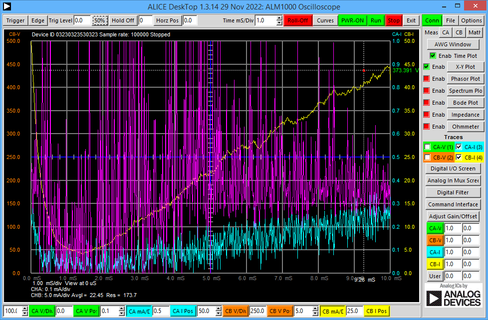
The cyan trace is the base current, the yellow trace is the resulting collector current, and the purple trace is the gain computed with the math function.

It's a mess because of all the noise on the lowish current (<1mA) that's driving the base.

There are a couple of other problems, too. One is that because I'm using a sawtooth waveform, the slew at the start messes up the first part of the curve. A second problem is that, as I don't know the gain ahead of time, I ended up adjusting the range the base current sweeps over to give a reasonable range on the collector current.

So, can I do better? Perhaps I can cobble together something with an op amp.

My next attempt was with this circuit.

image

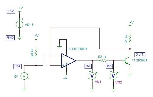
This is a form of driven bridge. An output pin (ChA) of the ADALM1000 sinks current through a 47R resistor. The op-amp compares the resulting voltage to that from a 47R dropping the collector current of the transistor and adjusts the transistor base drive to make them match. When the ADALM1000 sweeps the current, the collector current will follow, and it will be less noisy than before because the current is now up in the mA area. The base current I'm measuring with a resistor and the two inputs of the ADALM1000.

That results in this for the curves for a 2N3904 and a BC549C

image

It's quieter than before, but there's still noise. A disadvantage of doing a differential measurement using two inputs is that it doubles up the noise. A second (hidden) disadvantage is that the ADALM1000 inputs have quite a bit of capacitance (390pF, and whilst the op amp seems to manage, it's not ideal to have that hanging on its output)

Since it was a dual op amp, I decided to instead try a simple differential amplifier with the other half and then I would only need to use one input on the ADALM1000 driven from an op-amp output. Here's the circuit:

image

That gives me these curves.

image

It still suffers from the slew in the region up to 4mA, though, whilst it's still not exactly professional level, we're getting a better idea of the shape of the transistor characteristics now. I've thrown in a 2N2222A for good measure.

I wasn't expecting the hump in the curve for the BC549C, so that might indicate a problem of some sort with the test.

Here is the sweep extended up to 100mA:

image

Keep in mind that they will all be suffering from self-heating at the top end, the 2N3904 and the BC549C in particular where they are above the max dissipation limit. Also, because with my circuit the collector voltage falls with current, I'm not measuring at a constant Vc.

Hope that was of some interest. Although not spectacularly successful, it gives an idea of the kind of things that can be done with the device and a little extra circuitry.

Update 28th July 2023

I've reworked the circuit, to lose the embarrassing high-frequency oscillation (discussed in comments below), by building an integrator around the op amp like this:
image
Not sure that's the best way to compensate it, but it does seem to give enough extra phase margin at the top end to stop the oscillation and allow the op amp to do its job of mirroring at the transistor collector what is happening at the input.

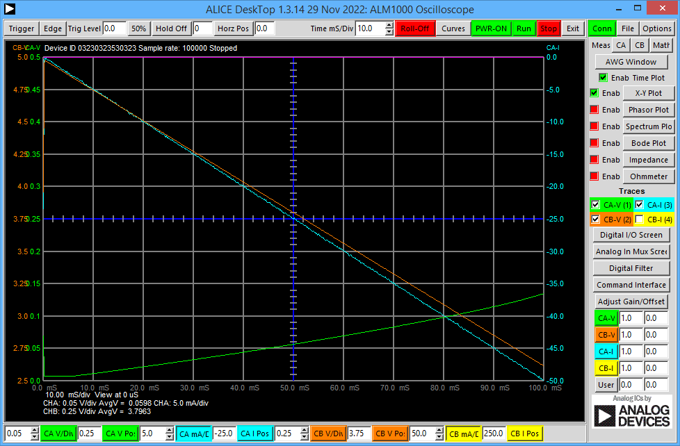
Here are the 'scope view' traces. Now the collector voltage trace (orange) is a straight line as the input sweeps the current [cyan trace]. The green trace is the output of the differential amplifier, where the resulting voltage is proportional to the transistor base current.


image


That gives this for the plot of transistor gain against collector current.


image


Leaving aside the mess up to about 5mA, the noise on the current output from the ADALM1000 affecting the calculation of the gain quite badly at lower currents, and the untidy lines from the 'fly-back' at the end, that's not too bad.

Previous blogs

A Short Informal Review of the ADALM1000 from Analog Devices

Experimenting With an All-Pass Filter using the ADALM1000 from Analog Devices

  • Sign in to reply

Top Comments

  • jc2048
    jc2048 over 2 years ago in reply to BigG +1
    Thank you. It's nice to know it was useful, though do remember that I'm just an old engineer 'noodling around' with stuff.
  • beacon_dave
    beacon_dave over 2 years ago in reply to jc2048

    "...Design looks like something from the XP era..."

    Perhaps this is why ?  Slight smile

    image

    from current product brief iCEcube2Brief.PDF

    • Cancel
    • Vote Up 0 Vote Down
    • Sign in to reply
    • More
    • Cancel
  • genebren
    genebren over 2 years ago

    Nice update.  Good detective work on finding/fixing the oscillations.  Looking better!

    • Cancel
    • Vote Up 0 Vote Down
    • Sign in to reply
    • More
    • Cancel
  • jc2048
    jc2048 over 2 years ago in reply to beacon_dave

    There's limits to what can be done with 1K logic elements, but some music should be possible.

    "I've not looked at iCECube2 yet..."

    It's simple, basic, and lightweight. Windows installer is only just over 700MB. Design looks like something from the XP era. It's also fast - you start it and it's just there, ready to go, like programs used to be. I like it, but it wouldn't be for everyone. Worst thing is probably the handover to the third-party simulator (currently ModelSim), which I still don't properly understand. Simulating the high-level VHDL is easy, because you can simply do it all within ModelSim, but I still don't quite get simulating after synthesis with it (it involves diving in and editing one of the handover files, would you believe). I'll have another go with it when I play with the ICEstick.

    • Cancel
    • Vote Up 0 Vote Down
    • Sign in to reply
    • More
    • Cancel
  • beacon_dave
    beacon_dave over 2 years ago in reply to shabaz

    I'm sure there are other annoying aspects as well Slight smile

    But if you are just starting out, then the ICE Studio user interface looks a lot less intimidating / less bloated than some of the current manufacturer's software.

    I suspect that you will end up having to learn both VHDL and Verilog to some extent as time goes on and have to move onto other software.

    • Cancel
    • Vote Up 0 Vote Down
    • Sign in to reply
    • More
    • Cancel
  • shabaz
    shabaz over 2 years ago in reply to beacon_dave

    Only annoying thing about the APIO/open source stuff is that it only supports Verilog. I think that's the same case for Ice Studio, but not checked. For VHDL, there's no complete open source solution, it needs the manufacturer software.

    • Cancel
    • Vote Up 0 Vote Down
    • Sign in to reply
    • More
    • Cancel
>
element14 Community

element14 is the first online community specifically for engineers. Connect with your peers and get expert answers to your questions.

  • Members
  • Learn
  • Technologies
  • Challenges & Projects
  • Products
  • Store
  • About Us
  • Feedback & Support
  • FAQs
  • Terms of Use
  • Privacy Policy
  • Legal and Copyright Notices
  • Sitemap
  • Cookies

An Avnet Company © 2026 Premier Farnell Limited. All Rights Reserved.

Premier Farnell Ltd, registered in England and Wales (no 00876412), registered office: Farnell House, Forge Lane, Leeds LS12 2NE.

ICP 备案号 10220084.

Follow element14

  • X
  • Facebook
  • linkedin
  • YouTube