I'll check when I get home tonight. According to the packing slip it is mk3880bn-l .But I'll check the chip when I get home. I do have a CTC I might try tonight. I do have 1.8432mhz crystal oscillators coming tomorrow. Yes. I remember thoes protocols. Lol. Blast from the past. Lol. Anyway. I haven't had much time to work on it much this week,. I have been doing a lot of reading though on the various chips. Thanks.
What is the exact part number of the Z80 you're using? It'd be like Z84xxx or Z84Cxxx for the later revisions.
This determines the electrical characteristics.
Not essential but common baud rate generator crystal frequencies are multiples of 1.8432 MHz - this something that is easily divisible to get most or all of the common baud rates.
In the old days baud rate generator ICs (or Z80 CTC) would be used to divide this frequency down to the desired bit rate. (These days they're inbuilt into embedded micros).
With the above crystal a divisor of 6144 yields 300 baud, 192 yields 9600 baud.
A good project to do is to write an X,Y or ZMODEM program to download and upload files.
Oh. Sorry . Just a terminal on my Linux machine. Not the old school dumb terminal . Want to get that running so I can write a monitor program type of thing and load/ dump memory.
I have a couple but I'm working with the z80b. I have everything working with a manual clock along with a555 time clock running at 20 hz. Above that it is too fast to figure out what itit doing . The can oscillator i have is a 7.something. It will drive a baud generator on a serial interface, but I think it is too fast for the 6850. I have a z8470 dart too and ordered a few things last night. I might try timing a 555 timer to generate a baud need nothin more than 2400 or even 1200 at the moment. I'm not sure how exact the baud generator needs to be to work with a terminal.
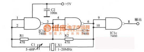
Two pin metal cans are just crystals. They require an accompanying circuit to make the them oscillate. The circuit can be as simple as two or three inverter gates with a couple of feed back resistors and a small ceramic capacitor.
The voltage across an oscillating crystal is small and the accompanying circuit will output a suitable or near suitable signal.
Here is an example circuit similar to that I used 35+ years ago. For a Z80, it is also necessary to add a 330 Ohm pull up resistor to the output to meet the required clock input specification.
You can of course use 7404 inverter gates in lieu of the 7400 NAND gates.
Some variance can be used with the resistors. I've used 1K.
C2 is just a ceramic (or monolythic) Coulomb bucket capacitor. (Others in correctly call it a bypass or decoupling cap but it's really there as a electron store because there's nothing being bypassed or decoupled).
C1 is a trimmer pot allow the output frequency to be adjusted
Four pin metal cans whether they be small or larger are often crystal oscillators. It is the crystal along with the necessary oscillator circuit. Only three pins are used. Voltage, Ground and Oscillator output.
To use it with a Z80 ensure that the output specifications are correct.
I started to use them but as a beginner, and using a breadboard(s), I opted to remove them as to the space, wiring, and debugging, was difficult . I will probably as them once I get a system running. I'm getting really close . I have the z80 reading instructions from room and writing to ram. I debugged that and to my surprise I worked after a few datalines crossed and a few address lines. Now working on the serial interface .
I have a question,. Might sound stupid, but I am a beginner. I have some full can crystal crystal oscillators . What is the difference between the full can 4 pin ones and the smaller 2 pins. I've googled it and I must have the search terms wrong because I can't find an answer. Do the full can ones have the capacitors built in? The datasheet I have form them tells me nothing but the pinouts. I've checked the output work my oscilloscope but I think the 7.3436? MHz is to fast for it and am not sure if I'm getting a sine wave or a distorted square wave. I have some 1mhz coming in the next few days off the same style and I'll check them. Thanks.
I now have a list of books in excel format - partial list, more to come - available if you want to see it. I can't see how I can upload it here, but I can always send it to you if you want. They are now with anybook.biz for sale if interested and are a mixture of old technology books, including Z80, 6502, Spectrum, ZX81, Amiga, etc etc.
Adding transceivers and buffers is a usual task for Z80 older designs when we used to use TTL.
The decision to use them depends upon the Z80 variant used.
I think the original NMOS variant can only handle IOL=+2mA and IOH--250uA (1 TTL or 4 LS loads) whereas the CMOS variant IOL=+2mA and IOH=-1.6mA so ensure your design does not exceed these fanout limits.
If you plan to use DRAM with DMA, you'll need to ensure that all bus masters continue to refresh the DRAM but I'm guessing you'll be using SRAM.