element14 Community
element14 Community
    Register Log In
  • Site
  • Search
  • Log In Register
  • Community Hub
    Community Hub
    • What's New on element14
    • Feedback and Support
    • Benefits of Membership
    • Personal Blogs
    • Members Area
    • Achievement Levels
  • Learn
    Learn
    • Ask an Expert
    • eBooks
    • element14 presents
    • Learning Center
    • Tech Spotlight
    • STEM Academy
    • Webinars, Training and Events
    • Learning Groups
  • Technologies
    Technologies
    • 3D Printing
    • FPGA
    • Industrial Automation
    • Internet of Things
    • Power & Energy
    • Sensors
    • Technology Groups
  • Challenges & Projects
    Challenges & Projects
    • Design Challenges
    • element14 presents Projects
    • Project14
    • Arduino Projects
    • Raspberry Pi Projects
    • Project Groups
  • Products
    Products
    • Arduino
    • Avnet & Tria Boards Community
    • Dev Tools
    • Manufacturers
    • Multicomp Pro
    • Product Groups
    • Raspberry Pi
    • RoadTests & Reviews
  • About Us
  • Store
    Store
    • Visit Your Store
    • Choose another store...
      • Europe
      •  Austria (German)
      •  Belgium (Dutch, French)
      •  Bulgaria (Bulgarian)
      •  Czech Republic (Czech)
      •  Denmark (Danish)
      •  Estonia (Estonian)
      •  Finland (Finnish)
      •  France (French)
      •  Germany (German)
      •  Hungary (Hungarian)
      •  Ireland
      •  Israel
      •  Italy (Italian)
      •  Latvia (Latvian)
      •  
      •  Lithuania (Lithuanian)
      •  Netherlands (Dutch)
      •  Norway (Norwegian)
      •  Poland (Polish)
      •  Portugal (Portuguese)
      •  Romania (Romanian)
      •  Russia (Russian)
      •  Slovakia (Slovak)
      •  Slovenia (Slovenian)
      •  Spain (Spanish)
      •  Sweden (Swedish)
      •  Switzerland(German, French)
      •  Turkey (Turkish)
      •  United Kingdom
      • Asia Pacific
      •  Australia
      •  China
      •  Hong Kong
      •  India
      • Japan
      •  Korea (Korean)
      •  Malaysia
      •  New Zealand
      •  Philippines
      •  Singapore
      •  Taiwan
      •  Thailand (Thai)
      • Vietnam
      • Americas
      •  Brazil (Portuguese)
      •  Canada
      •  Mexico (Spanish)
      •  United States
      Can't find the country/region you're looking for? Visit our export site or find a local distributor.
  • Translate
  • Profile
  • Settings
Community Hub
Community Hub
Member's Forum Doorbell Circuit Help
  • Blog
  • Forum
  • Documents
  • Quiz
  • Events
  • Leaderboard
  • Polls
  • Files
  • Members
  • Mentions
  • Sub-Groups
  • Tags
  • More
  • Cancel
  • New
Join Community Hub to participate - click to join for free!
Actions
  • Share
  • More
  • Cancel
Forum Thread Details
  • State Not Answered
  • Replies 14 replies
  • Subscribers 574 subscribers
  • Views 1338 views
  • Users 0 members are here
  • monostable
  • reed_switches
  • bell
Related

Doorbell Circuit Help

pathfider1998
pathfider1998 over 9 years ago

Hello, I am quite new here, so don't be too harsh.

If this is in the wrong community, tell me where to move this post to so I can get appropriate help.

-------------------------------------------


This specific problem has been bugging me for a long time.

*UPDATED*


So I have this little old doorbell which uses 3V battery and a generic Normally-open switch of any type to operate.

The doorbell rings when two wires coming from the unit is shorted (connected together).

Minimal duration for the activation is about 0.1ms.

When the switch is closed and held, it rings continuously (ding-dong, 0.5 second delay, ding-dong, delay again...)


I was using reed switch (normally-closed) to on a sliding automatic door so the bell rings when the door is opened.

The problem is, the door closes quite slowly because of the safety function (it has been installed so the door doesn't trap hands or other objects), so the doorbell rings 5~6 times constantly while the door closes.

I do not want to annoy people nor I want to drain the battery too fast.


I needed something to pulse the transistor or a relay for a brief moment (so the bell rings) and stays off until the door is closed.

So I searched for the monostable circuit that uses 3V or less as a power source. It returned none. (Or, they didn't work as desired)

I tried using some generic 555 timers, but they drew too much power (4.5V) and was not qualified.

I want to avoid using Arduino or ATTiny (or LSxxxx) because they cost a lot here.


UPDATE: Here's the explanation:

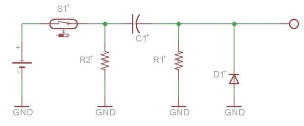
1. The reed switch is connected parallel to the power in (Vcc) of the control circuit we are trying to build.

So when the magnet is taken away and the reed switch closes, the control circuit kicks in, and when the door closes and reed switch opens, only the control circuit shuts off.

2. The pulse should be sent only once no matter how slow the door closes or where the door is at. There must be no second ringer.


It doesn't need to be tiny, just small enough to fit inside the credit card when built on a breadboard (ignore the heights).

Could anyone help?


p.s. E14 really needs some sort of "Without Code", "Newcomer Friendly", "Not-a-Coder" or "Logic Gates Only" group.

Somewhere where people like me can ask about the most cost-effective/fool-proof way to make things happen without programming PICs or using ready-made solutions.

Or for people without access to advanced components like ATTiny or LS74xx.


Or just make it easier for people to look for communities without having to scroll down 940 miles just to find the end of the list.

(Or maybe I am just silly. Tell me about communities or groups I can join too)


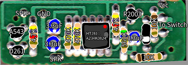
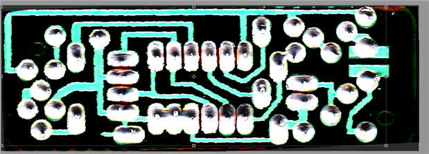
Here's the circuit board. Maybe you guys can understand this better.

image

image

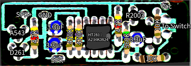
Plus: Pin 1 of IC marked, and components are highlighted.

image

  • Sign in to reply
  • Cancel

Top Replies

  • dougw
    dougw over 9 years ago +2
    It sounds like you want a directional switch that sends a single pulse if the door opens, but when it closes there is no pulse, just a reset. There are many ways to achieve this, even without chips ..…
  • gadget.iom
    gadget.iom over 9 years ago +1
    Hi Phil Welcome to the Element14 community. Does your reed switch go open or closed circuit when the door is opened?
  • D_Hersey
    D_Hersey over 9 years ago +1
    I think that a CMOS 555, such as lmc555 will work at the low potentials you require.
Parents
  • dougw
    0 dougw over 9 years ago

    It sounds like you want a directional switch that sends a single pulse if the door opens, but when it closes there is no pulse, just a reset.

    There are many ways to achieve this, even without chips .... one way is to use your reed switch like the circuit below:

    The switch is in the battery power wire so there is no power when the door is shut. When the door opens the switch closes and powers the circuit. On power up, the circuit generates a pulse with time constant R1C1.

    When the door closes nothing happens until switch 1 tuns off power to the circuit.

    R2 will bleed charge off the capacitor while the door is closed, getting ready for the next opening.

    D1 is just in case the ringer circuit can't take a 3 volt negative spike as the door closes, but if R2 is much bigger than R1, it is not needed.

    If you connect your ringer module power where R2 is and it takes some current continuously, then R2 is not needed.

    The circular terminal on the right is the pulse trigger for the ringer module.

    image

    Doug

    • Cancel
    • Vote Up +2 Vote Down
    • Sign in to reply
    • Verify Answer
    • Cancel
Reply
  • dougw
    0 dougw over 9 years ago

    It sounds like you want a directional switch that sends a single pulse if the door opens, but when it closes there is no pulse, just a reset.

    There are many ways to achieve this, even without chips .... one way is to use your reed switch like the circuit below:

    The switch is in the battery power wire so there is no power when the door is shut. When the door opens the switch closes and powers the circuit. On power up, the circuit generates a pulse with time constant R1C1.

    When the door closes nothing happens until switch 1 tuns off power to the circuit.

    R2 will bleed charge off the capacitor while the door is closed, getting ready for the next opening.

    D1 is just in case the ringer circuit can't take a 3 volt negative spike as the door closes, but if R2 is much bigger than R1, it is not needed.

    If you connect your ringer module power where R2 is and it takes some current continuously, then R2 is not needed.

    The circular terminal on the right is the pulse trigger for the ringer module.

    image

    Doug

    • Cancel
    • Vote Up +2 Vote Down
    • Sign in to reply
    • Verify Answer
    • Cancel
Children
  • pathfider1998
    0 pathfider1998 over 9 years ago in reply to dougw

    A slightly more detailed view:


    It uses Holtek HT2811 chip.

    It uses two transistors to drive a speaker.


    Circuit schematics will be uploaded too.

    • Cancel
    • Vote Up 0 Vote Down
    • Sign in to reply
    • Verify Answer
    • Cancel
element14 Community

element14 is the first online community specifically for engineers. Connect with your peers and get expert answers to your questions.

  • Members
  • Learn
  • Technologies
  • Challenges & Projects
  • Products
  • Store
  • About Us
  • Feedback & Support
  • FAQs
  • Terms of Use
  • Privacy Policy
  • Legal and Copyright Notices
  • Sitemap
  • Cookies

An Avnet Company © 2025 Premier Farnell Limited. All Rights Reserved.

Premier Farnell Ltd, registered in England and Wales (no 00876412), registered office: Farnell House, Forge Lane, Leeds LS12 2NE.

ICP 备案号 10220084.

Follow element14

  • X
  • Facebook
  • linkedin
  • YouTube