element14 Community
element14 Community
    Register Log In
  • Site
  • Search
  • Log In Register
  • Community Hub
    Community Hub
    • What's New on element14
    • Feedback and Support
    • Benefits of Membership
    • Personal Blogs
    • Members Area
    • Achievement Levels
  • Learn
    Learn
    • Ask an Expert
    • eBooks
    • element14 presents
    • Learning Center
    • Tech Spotlight
    • STEM Academy
    • Webinars, Training and Events
    • Learning Groups
  • Technologies
    Technologies
    • 3D Printing
    • FPGA
    • Industrial Automation
    • Internet of Things
    • Power & Energy
    • Sensors
    • Technology Groups
  • Challenges & Projects
    Challenges & Projects
    • Design Challenges
    • element14 presents Projects
    • Project14
    • Arduino Projects
    • Raspberry Pi Projects
    • Project Groups
  • Products and Partners
    Products and Partners
    • Arduino
    • Avnet & Tria Boards Community
    • Dev Tools
    • Manufacturers
    • Multicomp Pro
    • Product Groups
    • Raspberry Pi
    • RoadTests & Reviews
  • About Us
    About the element14 Community
  • Store
    Store
    • Visit Your Store
    • Choose another store...
      • Europe
      •  Austria (German)
      •  Belgium (Dutch, French)
      •  Bulgaria (Bulgarian)
      •  Czech Republic (Czech)
      •  Denmark (Danish)
      •  Estonia (Estonian)
      •  Finland (Finnish)
      •  France (French)
      •  Germany (German)
      •  Hungary (Hungarian)
      •  Ireland
      •  Israel
      •  Italy (Italian)
      •  Latvia (Latvian)
      •  
      •  Lithuania (Lithuanian)
      •  Netherlands (Dutch)
      •  Norway (Norwegian)
      •  Poland (Polish)
      •  Portugal (Portuguese)
      •  Romania (Romanian)
      •  Russia (Russian)
      •  Slovakia (Slovak)
      •  Slovenia (Slovenian)
      •  Spain (Spanish)
      •  Sweden (Swedish)
      •  Switzerland(German, French)
      •  Turkey (Turkish)
      •  United Kingdom
      • Asia Pacific
      •  Australia
      •  China
      •  Hong Kong
      •  India
      •  Japan
      •  Korea (Korean)
      •  Malaysia
      •  New Zealand
      •  Philippines
      •  Singapore
      •  Taiwan
      •  Thailand (Thai)
      •  Vietnam
      • Americas
      •  Brazil (Portuguese)
      •  Canada
      •  Mexico (Spanish)
      •  United States
      Can't find the country/region you're looking for? Visit our export site or find a local distributor.
  • Translate
  • Profile
  • Settings
Community Hub
Community Hub
Member's Forum Very low powered light help
  • Blog
  • Forum
  • Documents
  • Quiz
  • Events
  • Leaderboard
  • Polls
  • Files
  • Members
  • Mentions
  • Sub-Groups
  • Tags
  • More
  • Cancel
  • New
Join Community Hub to participate - click to join for free!
Actions
  • Share
  • More
  • Cancel
Forum Thread Details
  • State Suggested Answer
  • Replies 24 replies
  • Answers 12 answers
  • Subscribers 635 subscribers
  • Views 3247 views
  • Users 0 members are here
  • boost converter
  • light
Related

Very low powered light help

pathfider1998
pathfider1998 over 10 years ago

Hello again,
Here's a thing: I need to build something that takes generic 3V LEDs of (almost) any color, running at half+quarter (3/4) of its brightness, which uses generic components anyone can find in electronics components seller (like NPN transistor), takes 0.7V~1.5V, and lights LED until the sun comes up, which is about 6~10 hours.

It does not have to be using rechargeable batteries (it'll be great if they do however) but it must sense light so it turns off when the sun shines.

(Nobody likes to change batteries daily just to enjoy teeny tiny light)


It'll be almost mass-produced (~100 units, hand-assembled) so it needs to be very simple.

Its circuit will be based on matrix type breadboards (not Veroboard, which has strips of copper running along the rows) and it does not need to be very small.


Battery types will vary from generic AAA size cells to LR42/AG13 batteries.

Colors: Green / Blue / White / Warm White, 2.7V~3.3V <- This is not the voltage the boost converter should output! This is for reference only!

Since it will be running at half of its maximum brightness, the voltage could be lower.


More information:

The output of the boost converter ("joule thief") should be just enough to light a generic 3V LED just enough to be visible in a dark room (illuminating small area around it), as mentioned earlier.

It uses high intensity LEDs with clear lens (instead of diffused one). You know, those LEDs used in toys such as spinning tops.

The LEDs are running in limitless mode. (there are no current-limiting resistors)

The circuit could be very tiny in some cases. (1.3cm in diameter, excluding batteries)

It needs no smoothing. (30Hz~)

Manufacturing cost should be minimal as I can't order ready-made ICs now.


Updated: There were some misleading lines. They're fixed now. Sorry for the confusion!

  • Sign in to reply
  • Cancel
  • michaelkellett
    0 michaelkellett over 7 years ago in reply to st1

    This is not an efficient or cost effective way to light an LED !


    But it might be fun to play with if you have the bits to hand.


    MK

    • Cancel
    • Vote Up 0 Vote Down
    • Sign in to reply
    • Verify Answer
    • Reject Answer
    • Cancel
  • st1
    0 st1 over 7 years ago in reply to michaelkellett

    Hello !


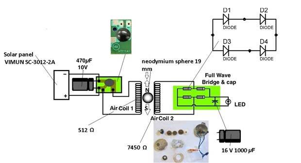
    My proposal is to start building first an electric motor which will run under low voltage and current. It will work 100 % because I build it ( it is my creation ).


    I have powered the electric  motor with a single Vimun Sc 3012  tiny solar panel and I managed to start it in the artificial light, using only 1,25 V and 0.054 ma....


    Here is the motor :

    You don't have permission to edit metadata of this video.
    Edit media
    x
    image
    Upload Preview
    image


    Then you will transform it in a generator (AC or DC )

    There is no converter, step up booster, joule thief, etc to start at the mentioned input ( 1,25 V and 0.054 ma )

    Increasing the voltage and current ( using a larger solar panel you will probably obtain what you are looking for  )

    You don't have permission to edit metadata of this video.
    Edit media
    x
    image
    Upload Preview
    image


    Here you will find all the construction details

    https://www.instructables.com/id/DC-Generator-Powered-With-a-Single-Mini-Solar-Pane/

    I used a led from a lamp scanner which can light blue, green and red ( depending pin connection )

    image

    Best regards ST


    The motor starts without help :

    You don't have permission to edit metadata of this video.
    Edit media
    x
    image
    Upload Preview
    image

    • Cancel
    • Vote Up +1 Vote Down
    • Sign in to reply
    • Verify Answer
    • Cancel
  • michaelkellett
    0 michaelkellett over 10 years ago in reply to pathfider1998

    Read some of the articles about how it works - it'll be worth it.


    It has to be a transformer - otherwise the transistor would stay on all the time.


    Digikey part number: ZXLD381FHCT-ND


    Farnell don't sell it, RS do.


    MK

    • Cancel
    • Vote Up 0 Vote Down
    • Sign in to reply
    • Verify Answer
    • Reject Answer
    • Cancel
  • pathfider1998
    0 pathfider1998 over 10 years ago in reply to michaelkellett

    Oh. Sorry. I forgot to tell you that I was talking about the "generic" version of the circuit using one transistor/FET, which uses center-tapped inductor for feedback(I guess).

    I was asking that in case I am unable to buy the IC from DigiKey or Mouser. Or E14 for that matter.

    • Cancel
    • Vote Up 0 Vote Down
    • Sign in to reply
    • Verify Answer
    • Cancel
  • michaelkellett
    0 michaelkellett over 10 years ago in reply to pathfider1998

    Sorry I'm not with you here:


    None of the links I gave you lead to using  a centre tapped inductor.


    The ZXLD381 is not a transistor - it's an IC.


    Could you explain to us what circuit you are trying to build.


    In general if a design require the use of  a centre tapped inductor then two separate inductors will not do because there is not mutual inductance (coupling) between them.


    MK

    • Cancel
    • Vote Up 0 Vote Down
    • Sign in to reply
    • Verify Answer
    • Cancel
  • pathfider1998
    0 pathfider1998 over 10 years ago in reply to michaelkellett

    Shifting topics here:


    1. It needs center-tapped inductor. Can I substitute it with a pair of "resistor-like" inductors? Like those used in RC circuits.

    2. Is C1815 applicable for the switching transistor? Otherwise I will have to order what you recommend.

    • Cancel
    • Vote Up 0 Vote Down
    • Sign in to reply
    • Verify Answer
    • Cancel
  • michaelkellett
    0 michaelkellett over 10 years ago

    Start here:


    https://en.wikipedia.org/wiki/Joule_thief


    Then look at this:


    www.diodes.com/_files/datasheets/ZXLD381.pdf


    Not perfect but close to what you want.


    Here's another:


    White LED is Powered by One NiMH Cell - LED_and_Light_Circuit - Circuit Diagram - SeekIC.com


    Google searches used:


    'single cell led driver chip'

    'joule thief analysis'


    MK

    • Cancel
    • Vote Up 0 Vote Down
    • Sign in to reply
    • Verify Answer
    • Reject Answer
    • Cancel
  • pathfider1998
    0 pathfider1998 over 10 years ago in reply to michaelkellett

    Could you explain why I can't use relaxation oscillator for this application? I am quite confused as many people out there were able to make RO run 3V LEDs, including those slightly high powered ones.

    Plus I am still a beginner. image


    p.s. The LED just needs to be lit dimly. Its minimum allowed current is 3/4 of "recommended driving current" of the LED I am going to use (as stated above).

    I am not saying I am going to run it with 3V 0.034mA output!

    • Cancel
    • Vote Up 0 Vote Down
    • Sign in to reply
    • Verify Answer
    • Cancel
  • michaelkellett
    0 michaelkellett over 10 years ago in reply to pathfider1998

    Phil, you need to define the problem and then look for solutions that actually solve it. Never rule anything out until you have evidence.


    Your problem is not that you need an up converter - you want to get  a constant current into your LED and that may need more or less volts than the battery. You can't do that with a relaxation oscillator (I can't bring myself to call it a J**** T**** !!). I doubt very much if you can do it starting from 0.7V without using some quite pricey parts (you'll need a bought in boost converter that can start from about 0.5V (to give  a working margin from your spec of 0.7V) and then a second switcher to drive the LED efficiently. It may be that someone makes a chip that does all this in one part but I don't know of one.


    Often you start out with a spec and need to refine it because it has internal conflicts - I think that in your case the 0.7V and the constraints on the type of parts you want to use might be such a conflict - so you'll need to change soothing to get it any further.


    MK

    • Cancel
    • Vote Up 0 Vote Down
    • Sign in to reply
    • Verify Answer
    • Reject Answer
    • Cancel
  • pathfider1998
    0 pathfider1998 over 10 years ago in reply to dougw

    3V, generic white LED, 25mA(+/-10%, since no spec sheet was given).

    Input voltage ranges from 0.7V to 3V.

    The term "high voltage" is used very generously -- It means it's just higher voltage.

    • Cancel
    • Vote Up 0 Vote Down
    • Sign in to reply
    • Verify Answer
    • Cancel
>
element14 Community

element14 is the first online community specifically for engineers. Connect with your peers and get expert answers to your questions.

  • Members
  • Learn
  • Technologies
  • Challenges & Projects
  • Products
  • Store
  • About Us
  • Feedback & Support
  • FAQs
  • Terms of Use
  • Privacy Policy
  • Legal and Copyright Notices
  • Sitemap
  • Cookies

An Avnet Company © 2026 Premier Farnell Limited. All Rights Reserved.

Premier Farnell Ltd, registered in England and Wales (no 00876412), registered office: Farnell House, Forge Lane, Leeds LS12 2NE.

Follow element14

  • X
  • Facebook
  • linkedin
  • YouTube