element14 Community
element14 Community
    Register Log In
  • Site
  • Search
  • Log In Register
  • Community Hub
    Community Hub
    • What's New on element14
    • Feedback and Support
    • Benefits of Membership
    • Personal Blogs
    • Members Area
    • Achievement Levels
  • Learn
    Learn
    • Ask an Expert
    • eBooks
    • element14 presents
    • Learning Center
    • Tech Spotlight
    • STEM Academy
    • Webinars, Training and Events
    • Learning Groups
  • Technologies
    Technologies
    • 3D Printing
    • FPGA
    • Industrial Automation
    • Internet of Things
    • Power & Energy
    • Sensors
    • Technology Groups
  • Challenges & Projects
    Challenges & Projects
    • Design Challenges
    • element14 presents Projects
    • Project14
    • Arduino Projects
    • Raspberry Pi Projects
    • Project Groups
  • Products
    Products
    • Arduino
    • Avnet & Tria Boards Community
    • Dev Tools
    • Manufacturers
    • Multicomp Pro
    • Product Groups
    • Raspberry Pi
    • RoadTests & Reviews
  • About Us
  • Store
    Store
    • Visit Your Store
    • Choose another store...
      • Europe
      •  Austria (German)
      •  Belgium (Dutch, French)
      •  Bulgaria (Bulgarian)
      •  Czech Republic (Czech)
      •  Denmark (Danish)
      •  Estonia (Estonian)
      •  Finland (Finnish)
      •  France (French)
      •  Germany (German)
      •  Hungary (Hungarian)
      •  Ireland
      •  Israel
      •  Italy (Italian)
      •  Latvia (Latvian)
      •  
      •  Lithuania (Lithuanian)
      •  Netherlands (Dutch)
      •  Norway (Norwegian)
      •  Poland (Polish)
      •  Portugal (Portuguese)
      •  Romania (Romanian)
      •  Russia (Russian)
      •  Slovakia (Slovak)
      •  Slovenia (Slovenian)
      •  Spain (Spanish)
      •  Sweden (Swedish)
      •  Switzerland(German, French)
      •  Turkey (Turkish)
      •  United Kingdom
      • Asia Pacific
      •  Australia
      •  China
      •  Hong Kong
      •  India
      • Japan
      •  Korea (Korean)
      •  Malaysia
      •  New Zealand
      •  Philippines
      •  Singapore
      •  Taiwan
      •  Thailand (Thai)
      • Vietnam
      • Americas
      •  Brazil (Portuguese)
      •  Canada
      •  Mexico (Spanish)
      •  United States
      Can't find the country/region you're looking for? Visit our export site or find a local distributor.
  • Translate
  • Profile
  • Settings
Community Hub
Community Hub
Member's Forum I think this is a buck converter, but I'm not entirely sure.
  • Blog
  • Forum
  • Documents
  • Quiz
  • Events
  • Leaderboard
  • Polls
  • Files
  • Members
  • Mentions
  • Sub-Groups
  • Tags
  • More
  • Cancel
  • New
Join Community Hub to participate - click to join for free!
Actions
  • Share
  • More
  • Cancel
Forum Thread Details
  • State Verified Answer
  • Replies 18 replies
  • Answers 3 answers
  • Subscribers 567 subscribers
  • Views 1935 views
  • Users 0 members are here
Related

I think this is a buck converter, but I'm not entirely sure.

capacitance_incarnate
capacitance_incarnate over 8 years ago

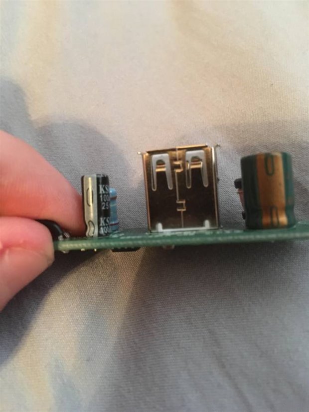
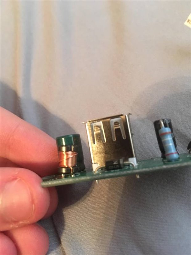
So I have this little chip here from a cigarette lighter psu, but there isn't a voltage regulator any where in it. If this is indeed a buck converter, that would explain the lack of a regulator, but I'm new to this kind of stuff, (I first got into it  while creating a project for school last year) so I would appreciate any help I can get.

imageimageimage

  • Sign in to reply
  • Cancel

Top Replies

  • rachaelp
    rachaelp over 8 years ago in reply to capacitance_incarnate +2 suggested
    Take a look at the datasheet for the controller here (assuming it is the one Shabaz is referring to): http://www.farnell.com/datasheets/1723944.pdf?_ga=1.226316314.1698039299.1446112257 If you look at…
  • shabaz
    shabaz over 8 years ago +1 verified
    Hi Jake, That is a voltage regulator, also known as a DC-DC converter or a Buck converter when it uses an inductor and switching and steps down the voltage. You could confirm by examining the part code…
  • rachaelp
    rachaelp over 8 years ago in reply to capacitance_incarnate +1
    Jake Linville wrote: ok so the big resistor up top is a 0.39 Ω ± 2%. I'm assuming thats the one that I need to replace, because there is no way I could replace the little ones on the bottom. Unfortunately…
Parents
  • shabaz
    0 shabaz over 8 years ago

    Hi Jake,


    That is a voltage regulator, also known as a DC-DC converter or a Buck converter when it uses an inductor and switching and steps down the voltage.

    You could confirm by examining the part code on the integrated circuit, and obtain the datasheet for the part online. It is extremely likely to be MC34063 (or similar) because that is common in low-cost USB car chargers (and from the photo, the pinout looks about right for that).

    • Cancel
    • Vote Up +1 Vote Down
    • Sign in to reply
    • Verify Answer
    • Reject Answer
    • Cancel
  • capacitance_incarnate
    0 capacitance_incarnate over 8 years ago in reply to shabaz

    Thanks so much! I'm assuming the input voltage would be 12v, yes? Also, is there anyway i can change the output voltage? I'd like to lower it to around 4.7 volts.

    • Cancel
    • Vote Up 0 Vote Down
    • Sign in to reply
    • Verify Answer
    • Cancel
  • rachaelp
    0 rachaelp over 8 years ago in reply to capacitance_incarnate

    Take a look at the datasheet for the controller here (assuming it is the one Shabaz is referring to): http://www.farnell.com/datasheets/1723944.pdf?_ga=1.226316314.1698039299.1446112257


    If you look at Figure 15 on page 11 this is the circuit for a step down converter. In the circuit in this drawing R1 and R2 are the feedback resistors which are used to set the output voltage. The CII input feeds into a comparator inside the device, the other input being a 1.25V reference. The device will try and adjust the output such that the voltage on the CII input matches the reference voltage so if you want to change your output voltage then select values of R1 and R2 such that CII is at 1.25V for your desired output voltage.


    Best Regards,


    Rachael

    • Cancel
    • Vote Up +2 Vote Down
    • Sign in to reply
    • Verify Answer
    • Reject Answer
    • Cancel
  • capacitance_incarnate
    0 capacitance_incarnate over 8 years ago in reply to rachaelp

    ok so the big resistor up top is a 0.39 Ω ± 2%. I'm assuming thats the one that I need to replace, because there is no way I could replace the little ones on the bottom., and to figure out what I need to replace the top one with, i need to figure out the bottom resistors and plug them into that equasion thing. (cant seem to find it right now. anyone know it?)

    • Cancel
    • Vote Up 0 Vote Down
    • Sign in to reply
    • Verify Answer
    • Cancel
Reply
  • capacitance_incarnate
    0 capacitance_incarnate over 8 years ago in reply to rachaelp

    ok so the big resistor up top is a 0.39 Ω ± 2%. I'm assuming thats the one that I need to replace, because there is no way I could replace the little ones on the bottom., and to figure out what I need to replace the top one with, i need to figure out the bottom resistors and plug them into that equasion thing. (cant seem to find it right now. anyone know it?)

    • Cancel
    • Vote Up 0 Vote Down
    • Sign in to reply
    • Verify Answer
    • Cancel
Children
  • rachaelp
    0 rachaelp over 8 years ago in reply to capacitance_incarnate

    Jake Linville wrote:


    ok so the big resistor up top is a 0.39 Ω ± 2%. I'm assuming thats the one that I need to replace, because there is no way I could replace the little ones on the bottom.

    Unfortunately that would be a bad assumption and the reason for the assumption is not good either image


    The 0.39 Ohm resistor is the current sense resistor for the active current limit. This equates to Rsc from Figure 15. So if you want to adjust the output voltage of this regulator you'll need to get yourself a decent soldering station and learn how to replace surface mount resistors yourself I'm afraid, unless you know anybody else than can do it for you.


    Best Regards,


    Rachael

    • Cancel
    • Vote Up +1 Vote Down
    • Sign in to reply
    • Verify Answer
    • Cancel
  • capacitance_incarnate
    0 capacitance_incarnate over 8 years ago in reply to rachaelp

    ok so I've located r1. its 1.2Ω. Im still working on r2. once i find that, ill plug it into that equation that Texas instruments has, and I'll replace r1. and issues in doing that?

    • Cancel
    • Vote Up 0 Vote Down
    • Sign in to reply
    • Verify Answer
    • Cancel
  • rachaelp
    0 rachaelp over 8 years ago in reply to capacitance_incarnate

    I hope it's not 1.2 ohm. Do you mean Kohm? You can do as you said to calculate the two resistor values. You might need to replace both to get the output you need as you will be restricted to standard values which can be easily obtained.

    • Cancel
    • Vote Up +1 Vote Down
    • Sign in to reply
    • Verify Answer
    • Reject Answer
    • Cancel
  • capacitance_incarnate
    0 capacitance_incarnate over 8 years ago in reply to rachaelp

    whoops. yea i meant  kohms. I found what I belive to be r1, its a .43 kohm and a 3.3 kohm in series, so if at all possible i want to try to only mess with r1.

    • Cancel
    • Vote Up 0 Vote Down
    • Sign in to reply
    • Verify Answer
    • Cancel
element14 Community

element14 is the first online community specifically for engineers. Connect with your peers and get expert answers to your questions.

  • Members
  • Learn
  • Technologies
  • Challenges & Projects
  • Products
  • Store
  • About Us
  • Feedback & Support
  • FAQs
  • Terms of Use
  • Privacy Policy
  • Legal and Copyright Notices
  • Sitemap
  • Cookies

An Avnet Company © 2025 Premier Farnell Limited. All Rights Reserved.

Premier Farnell Ltd, registered in England and Wales (no 00876412), registered office: Farnell House, Forge Lane, Leeds LS12 2NE.

ICP 备案号 10220084.

Follow element14

  • X
  • Facebook
  • linkedin
  • YouTube