element14 Community
element14 Community
    Register Log In
  • Site
  • Search
  • Log In Register
  • Community Hub
    Community Hub
    • What's New on element14
    • Feedback and Support
    • Benefits of Membership
    • Personal Blogs
    • Members Area
    • Achievement Levels
  • Learn
    Learn
    • Ask an Expert
    • eBooks
    • element14 presents
    • Learning Center
    • Tech Spotlight
    • STEM Academy
    • Webinars, Training and Events
    • Learning Groups
  • Technologies
    Technologies
    • 3D Printing
    • FPGA
    • Industrial Automation
    • Internet of Things
    • Power & Energy
    • Sensors
    • Technology Groups
  • Challenges & Projects
    Challenges & Projects
    • Design Challenges
    • element14 presents Projects
    • Project14
    • Arduino Projects
    • Raspberry Pi Projects
    • Project Groups
  • Products
    Products
    • Arduino
    • Avnet & Tria Boards Community
    • Dev Tools
    • Manufacturers
    • Multicomp Pro
    • Product Groups
    • Raspberry Pi
    • RoadTests & Reviews
  • About Us
    About the element14 Community
  • Store
    Store
    • Visit Your Store
    • Choose another store...
      • Europe
      •  Austria (German)
      •  Belgium (Dutch, French)
      •  Bulgaria (Bulgarian)
      •  Czech Republic (Czech)
      •  Denmark (Danish)
      •  Estonia (Estonian)
      •  Finland (Finnish)
      •  France (French)
      •  Germany (German)
      •  Hungary (Hungarian)
      •  Ireland
      •  Israel
      •  Italy (Italian)
      •  Latvia (Latvian)
      •  
      •  Lithuania (Lithuanian)
      •  Netherlands (Dutch)
      •  Norway (Norwegian)
      •  Poland (Polish)
      •  Portugal (Portuguese)
      •  Romania (Romanian)
      •  Russia (Russian)
      •  Slovakia (Slovak)
      •  Slovenia (Slovenian)
      •  Spain (Spanish)
      •  Sweden (Swedish)
      •  Switzerland(German, French)
      •  Turkey (Turkish)
      •  United Kingdom
      • Asia Pacific
      •  Australia
      •  China
      •  Hong Kong
      •  India
      •  Japan
      •  Korea (Korean)
      •  Malaysia
      •  New Zealand
      •  Philippines
      •  Singapore
      •  Taiwan
      •  Thailand (Thai)
      •  Vietnam
      • Americas
      •  Brazil (Portuguese)
      •  Canada
      •  Mexico (Spanish)
      •  United States
      Can't find the country/region you're looking for? Visit our export site or find a local distributor.
  • Translate
  • Profile
  • Settings
Community Hub
Community Hub
Member's Forum Best way to regulate electricity
  • Blog
  • Forum
  • Documents
  • Quiz
  • Events
  • Leaderboard
  • Polls
  • Files
  • Members
  • Mentions
  • Sub-Groups
  • Tags
  • More
  • Cancel
  • New
Join Community Hub to participate - click to join for free!
Actions
  • Share
  • More
  • Cancel
Forum Thread Details
  • State Suggested Answer
  • Replies 4 replies
  • Answers 3 answers
  • Subscribers 597 subscribers
  • Views 563 views
  • Users 0 members are here
  • build the thing
  • leds
  • mysterious box
  • don't blow up the thing
  • voltage regulation
Related

Best way to regulate electricity

malus_lupus
malus_lupus over 7 years ago

I plan to build this sorta complex I guess box or wall. Not really that complex but can be considered that. I was wondering something. This wall will have LEDs on it probably one for the top row and one for the bottom. I would like to have one for each unit but I suspect what is required for one LED is not something I can do for all parts since I probably do not have enough components.

The question is of course what is the best way to regulate voltage to an LED when the input voltage varies from 0-30 volts. I know resistor is out, so too is POTs, the only thing I can think of is a voltage regulator at 5 volts of course. However, I want to make sure, also if I should build a specific circuit and such. Probably need to make or add a heatsink as well right?

Then again if I do this right I could really only need two for all the LEDs on the top row and on the bottom.

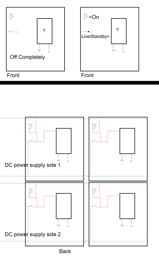
If you need an explanation of what I am making it is hard to explain but basically I am making units. Each one has a different object on it per se, a switch, a dp dt reverse polarity switch, pot, headphone jack and such for when I have different things needing different testing. Each unit I would want will have an LED and a knob with a piece of metal attached to it so I can close the circuit when I want. You could say a dirty switch. Easier and cheaper to make one than to keep using switches. The prototype was cardboard to see how to do it and if I can I will use a 3D printer to make the real deal. I know some people like explanations.

I was planning to cross the LED with each unit so when I turn the unit on it lights up so I know it is live. Which is possible to do with two regulators if not just one. I have to add more wires but yeah. The thing is I want to make sure it is just a regulator with a heat sink or should I add things like caps, and resistors for x purposes I know nothing about. The power supply is DC almost forgot. The LEDs from the datasheet which may be slightly inaccurate says 5 volts is sufficient.


  • Sign in to reply
  • Cancel

Top Replies

  • DAB
    DAB over 7 years ago +3 suggested
    Hi Justin, It all depends upon what you want the LED's to do. If you want a constant brightness during the different input voltages, then you want to maintain a constant current with a minimum voltage…
  • shabaz
    shabaz over 7 years ago +2 suggested
    Hi Justin, It's not entirely clear (a sketch may help, or a diagram showing the connections on each object. Reading between the lines, it sounds like some modular electronics kit, with connections at each…
  • malus_lupus
    malus_lupus over 7 years ago in reply to malus_lupus +1
    Maybe an LED dedicated line. With a regulator on one end and the line connects to all the LEDs but not back to the mainline. I think Yeah Makes sense it can work.
Parents
  • shabaz
    0 shabaz over 7 years ago

    Hi Justin,


    It's not entirely clear (a sketch may help, or a diagram showing the connections on each object. Reading between the lines, it sounds like some modular electronics kit, with connections at each end, that will join up when you attach them? And each module has two LEDs?


    If so, then if you're supplying power only from one end (e.g. both 0V and 30V connections) then you can (if you desire) have the LEDs effectively in parallel whenever the modules are joined, provided there are at least two connections (0V and 30V) on each of the two sides that attach to other modules.


    If you're supplying 30V from one end of a chain of modules, and 0V from the far end of that chain of modules, then I guess you're considering a serial chain of LEDs? If so, your design is a lot more complicated, it will require a constant current regulator. The parallel method could be achieved by having a resistor in series with each LED.


    For the parallel scenario resistor calculation, see here: LED series parallel array wizard

    For the parallel LEDs, your parameters to enter at that website are:

    Source voltage=30

    Diode forward voltage=2.5  (very unlikely that it will be 5V, but check your datasheet)

    Diode forward current=5  (5mA is a guess - usually works for small LEDs)

    Number of LEDs in array=1 (this is set to a higher value for series, but for the parallel scenario set it to 1 regardless of how many parallel LEDs you have - each parallel LED will have a series resistor of course).

    When you click the button, it will show you that you need a 5600 ohm resistor per LED. You could work this out using: R=(V-Vf)/I if you wished, no need to use the website. Where V=30, Vf=2.5V, and I=5mA.

    • Cancel
    • Vote Up +2 Vote Down
    • Sign in to reply
    • Verify Answer
    • Reject Answer
    • Cancel
  • malus_lupus
    0 malus_lupus over 7 years ago in reply to shabaz

    I may have drawn it up slightly off a bit but I drew it from memory since I do not have the prototype laying around. However, it seems accurate as in the circuit connects.


    Each unit can click into place like modules and as seen by the schematic per se they connect up where they can get power and such. The big question mark box with live and ground on it is a stand-in for whatever I put in it be it headphone jack, dp dt reverse polarity switch etc which will have wires coming off it with clips or other things. The bottom image shows the back. My DC power supply has two sides so I can just assign the top to one side and the bottom to another so I can use two things at once if need be. This will be a rare case of having to use two but still a possibility. Actually, I can keep my solder fan running with this method if I think about it and use the other one for something else. Basically when the switch is flipped/live the LED comes on so I know that module is working and is on. I think by this schematic others will not turn on but I have to re-examine it to make sure (yeah looks it).

    As stated I put a module in my head and picture it being plugged in and how the wires should be etc for it to work that way and stacking them on top of one another and such. I am a very visual person but my brain is not always clear when imagining stuff.

    (The dirty switch that you can see here will just be a piece of plastic with a metal tab on it that hooks onto another one as stated also. Since I can 3D print I can make this work aptly. Well, I hope this helps. Seems simple. I think a regulator at the very beginning of the circuit is the answer but then I need to split it a certain way where the x-30v goes to the switch and the regulator. Picturing this is making my head hurt)


    image

    • Cancel
    • Vote Up 0 Vote Down
    • Sign in to reply
    • Verify Answer
    • Reject Answer
    • Cancel
Reply
  • malus_lupus
    0 malus_lupus over 7 years ago in reply to shabaz

    I may have drawn it up slightly off a bit but I drew it from memory since I do not have the prototype laying around. However, it seems accurate as in the circuit connects.


    Each unit can click into place like modules and as seen by the schematic per se they connect up where they can get power and such. The big question mark box with live and ground on it is a stand-in for whatever I put in it be it headphone jack, dp dt reverse polarity switch etc which will have wires coming off it with clips or other things. The bottom image shows the back. My DC power supply has two sides so I can just assign the top to one side and the bottom to another so I can use two things at once if need be. This will be a rare case of having to use two but still a possibility. Actually, I can keep my solder fan running with this method if I think about it and use the other one for something else. Basically when the switch is flipped/live the LED comes on so I know that module is working and is on. I think by this schematic others will not turn on but I have to re-examine it to make sure (yeah looks it).

    As stated I put a module in my head and picture it being plugged in and how the wires should be etc for it to work that way and stacking them on top of one another and such. I am a very visual person but my brain is not always clear when imagining stuff.

    (The dirty switch that you can see here will just be a piece of plastic with a metal tab on it that hooks onto another one as stated also. Since I can 3D print I can make this work aptly. Well, I hope this helps. Seems simple. I think a regulator at the very beginning of the circuit is the answer but then I need to split it a certain way where the x-30v goes to the switch and the regulator. Picturing this is making my head hurt)


    image

    • Cancel
    • Vote Up 0 Vote Down
    • Sign in to reply
    • Verify Answer
    • Reject Answer
    • Cancel
Children
  • malus_lupus
    0 malus_lupus over 7 years ago in reply to malus_lupus

    Maybe an LED dedicated line. With a regulator on one end and the line connects to all the LEDs but not back to the mainline. I think Yeah Makes sense it can work.

    • Cancel
    • Vote Up +1 Vote Down
    • Sign in to reply
    • Verify Answer
    • Cancel
element14 Community

element14 is the first online community specifically for engineers. Connect with your peers and get expert answers to your questions.

  • Members
  • Learn
  • Technologies
  • Challenges & Projects
  • Products
  • Store
  • About Us
  • Feedback & Support
  • FAQs
  • Terms of Use
  • Privacy Policy
  • Legal and Copyright Notices
  • Sitemap
  • Cookies

An Avnet Company © 2026 Premier Farnell Limited. All Rights Reserved.

Premier Farnell Ltd, registered in England and Wales (no 00876412), registered office: Farnell House, Forge Lane, Leeds LS12 2NE.

ICP 备案号 10220084.

Follow element14

  • X
  • Facebook
  • linkedin
  • YouTube