element14 Community
element14 Community
    Register Log In
  • Site
  • Search
  • Log In Register
  • About Us
  • Community Hub
    Community Hub
    • What's New on element14
    • Feedback and Support
    • Benefits of Membership
    • Personal Blogs
    • Members Area
    • Achievement Levels
  • Learn
    Learn
    • Ask an Expert
    • eBooks
    • element14 presents
    • Learning Center
    • Tech Spotlight
    • STEM Academy
    • Webinars, Training and Events
    • Learning Groups
  • Technologies
    Technologies
    • 3D Printing
    • FPGA
    • Industrial Automation
    • Internet of Things
    • Power & Energy
    • Sensors
    • Technology Groups
  • Challenges & Projects
    Challenges & Projects
    • Design Challenges
    • element14 presents Projects
    • Project14
    • Arduino Projects
    • Raspberry Pi Projects
    • Project Groups
  • Products
    Products
    • Arduino
    • Avnet Boards Community
    • Dev Tools
    • Manufacturers
    • Multicomp Pro
    • Product Groups
    • Raspberry Pi
    • RoadTests & Reviews
  • Store
    Store
    • Visit Your Store
    • Choose another store...
      • Europe
      •  Austria (German)
      •  Belgium (Dutch, French)
      •  Bulgaria (Bulgarian)
      •  Czech Republic (Czech)
      •  Denmark (Danish)
      •  Estonia (Estonian)
      •  Finland (Finnish)
      •  France (French)
      •  Germany (German)
      •  Hungary (Hungarian)
      •  Ireland
      •  Israel
      •  Italy (Italian)
      •  Latvia (Latvian)
      •  
      •  Lithuania (Lithuanian)
      •  Netherlands (Dutch)
      •  Norway (Norwegian)
      •  Poland (Polish)
      •  Portugal (Portuguese)
      •  Romania (Romanian)
      •  Russia (Russian)
      •  Slovakia (Slovak)
      •  Slovenia (Slovenian)
      •  Spain (Spanish)
      •  Sweden (Swedish)
      •  Switzerland(German, French)
      •  Turkey (Turkish)
      •  United Kingdom
      • Asia Pacific
      •  Australia
      •  China
      •  Hong Kong
      •  India
      •  Korea (Korean)
      •  Malaysia
      •  New Zealand
      •  Philippines
      •  Singapore
      •  Taiwan
      •  Thailand (Thai)
      • Americas
      •  Brazil (Portuguese)
      •  Canada
      •  Mexico (Spanish)
      •  United States
      Can't find the country/region you're looking for? Visit our export site or find a local distributor.
  • Translate
  • Profile
  • Settings
Community Hub
Community Hub
Member's Forum Improving a Reflectance Sensor design for high speed reading
  • Blog
  • Forum
  • Documents
  • Quiz
  • Events
  • Leaderboard
  • Polls
  • Files
  • Members
  • Mentions
  • Sub-Groups
  • Tags
  • More
  • Cancel
  • New
Join Community Hub to participate - click to join for free!
Actions
  • Share
  • More
  • Cancel
Forum Thread Details
  • State Suggested Answer
  • Replies 9 replies
  • Answers 5 answers
  • Subscribers 534 subscribers
  • Views 2008 views
  • Users 0 members are here
  • analog input
  • tachometer
  • encoder
  • comparator
  • lm393
  • ir sensor
  • analog
  • darlington pair
Related

Improving a Reflectance Sensor design for high speed reading

luislabmo
luislabmo over 5 years ago

I've been prototyping with a Reflectance Sensor to be used in different applications with a micro-controller, mostly as a speed sensor and as an encoder. My goal is to try to use it as best as I can at high speeds which at the end of the day is just reading Reflectance -or Not- for pulses that last a very short amount of time. Below is the Schematic in question - this design is not originally mine but seems to be the go-to design for many hobbyist IR Sensors.

image

First I tried working with just the circuit enclosed inside the Reflective Object Sensor area which produces an analog signal, but at high speeds the signal doesn't rise fast enough, with that in mind, leaving out the Comparator (LM393) or any solution that helps mitigate this problem is probably out of the question.


  1. Low Speed test: to my surprise, I noticed that the LED helps in the design image. It helps the signal rise faster or makes it look more like a square wave -which is a good thing as I'm reading the output using an external interrupt. I noticed when the LED (D1) is replaced with any diode, the output looks even better (on the downside it adds a ringing to the base voltage). Could someone explain why a Diode seems to help here? and why, as I increase the value of R5, the Base voltage tends to be lower? -again another good thing for the design seems. In this test I tried different diodes 1N5227B Zenner Diode1N5227B Zenner Diode, 1N914 Signal Diode1N914 Signal Diode and 1N4007 all with the same results.
    image
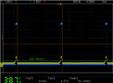
  2. High Speed test: It seems that the current value of C3 is too high and affects the output when the sensor is reading reflectance at high-speeds (the pulses don't rise high or fast enough for the micro-controller to read High). In that case, what could be a better trade off? - adding the Diode and/or lowering C3 to lets say 0.01µF.
    image
  3. Keeping the LED: adding the Diode seems to be a good approach -or maybe there is a different way-. What could be the best way of keeping the LED also? -It's a great way to have a visual feedback when the sensor is doing it's job and also to help calibrating the sensor.


If you made it this far, thank you for reading. Please let me know what you think in the comments.


Luis

  • Sign in to reply
  • Cancel

Top Replies

  • dougw
    dougw over 5 years ago +4 suggested
    The rise time is governed by the time constant formed by C3 and the combination of R2 and R5. Because R5 is smaller than R2, when it is in the circuit (when the diode is in the circuit) the rise time will…
  • shabaz
    shabaz over 5 years ago +4 suggested
    Hi Luis! There's a few things to try: Firstly (very important) there needs to be a 100nF capacitor* directly across the supply rails of U1. You may already have done this (it's not on the circuit diagram…
  • neuromodulator
    neuromodulator over 5 years ago +4 suggested
    Improving the response of the comparator is important but so is improving the photo-transistor response. Don't forget about the miller effect, try reducing R to a max of R = VCC / 50ma. You will trade…
  • dougw
    0 dougw over 5 years ago

    The rise time is governed by the time constant formed by C3 and the combination of R2 and R5.

    Because R5 is smaller than R2, when it is in the circuit (when the diode is in the circuit) the rise time will be shorter.

    If you short out the LED the rise time will be even shorter.

    If the resistance is small - where the current through it is the max the output can sink, the rise time will be shortest.

    Open drain comparators will always suffer if there is capacitance on the output.

    If you remove the capacitor (C3) and the ringing is too severe, try clamping it with low capacitance diodes or zeners.

    Or you can use a push-pull comparator which will have faster rise times.

    • Cancel
    • Vote Up +4 Vote Down
    • Sign in to reply
    • Verify Answer
    • Reject Answer
    • Cancel
  • shabaz
    0 shabaz over 5 years ago

    Hi Luis!


    There's a few things to try:

    Firstly (very important) there needs to be a 100nF capacitor* directly across the supply rails of U1. You may already have done this (it's not on the circuit diagram).

    I sometimes wire it diagonally across the chip, to keep the leads short (example photo below of a different chip, but you can see how it is placed on top of the chip to keep the length as short as possible).

    Also, D1, R5 and C3 are not needed, if you're connecting to a microcontroller. However, try reducing R3 from 10k to (say) 1k to see if it improves things. The current consumption will increase, but this isn't so significant in this circuit because the LED in the reflectance device will be using more current anyway.

    Also, the datasheet suggests implementing hysteresis, as in figure 22 of the TI datasheet.

    Finally, if this is on breadboard, maybe shorter wires could help.


    * 100nF axial capacitors100nF axial capacitors are convenient for wiring across the chip, but really any 100nF capacitor will do.


    EDIT: Also, if there is an unused comparator in that chip as there seems to be from the schematic, then you can connect one input to ground (via say a 1k resistor) and another input to the supply (via another 1k resistor) so that no output circuitry for the unused comparator is (potentially) unstable.


    image

    • Cancel
    • Vote Up +4 Vote Down
    • Sign in to reply
    • Verify Answer
    • Reject Answer
    • Cancel
  • neuromodulator
    0 neuromodulator over 5 years ago

    Improving the response of the comparator is important but so is improving the photo-transistor response. Don't forget about the miller effect, try reducing R to a max of R = VCC / 50ma. You will trade response amplification for speed.

    • Cancel
    • Vote Up +4 Vote Down
    • Sign in to reply
    • Verify Answer
    • Reject Answer
    • Cancel
  • luislabmo
    0 luislabmo over 5 years ago in reply to dougw

    Hi Doug!.


    Thanks for the suggestion on the push-pull comparator. Any spec (or characteristic) I should target for?


    Luis

    • Cancel
    • Vote Up +2 Vote Down
    • Sign in to reply
    • Verify Answer
    • Cancel
  • luislabmo
    0 luislabmo over 5 years ago in reply to shabaz

    Hi Shabaz!.


    You guessed well, I'm using a breadboard and that's one the reasons there is considerable noise in the screen captures -actually is my first time ever with an analog circuit and using a comparator, naturally I didn't feel comfortable going directly to a PCB design without trying it first with a spiderweb of wires.


    I removed the components you suggested and added the hysteresis, the signal changes real fast... nice catch from your side, Thank you!  -Still trying to understand the formulas as seems hysteresis in my case only works when the resistor in series with the input is added (red arrow in the diagram)

    image

    Let me ask one more. I'm planning -hopefully- to use the sensor in some noisy environments with motors and maybe some long wires (2 or 3 feet long). Is it better practice to include the sensor and the comparator close the motor (sending the comparator's output through the wires) or should I keep the comparator closer to the micro-controller? in which case the IR sensor output would be the one traveling through the wires.


    Luis

    • Cancel
    • Vote Up +2 Vote Down
    • Sign in to reply
    • Verify Answer
    • Cancel
  • shabaz
    0 shabaz over 5 years ago in reply to luislabmo

    Hi Luis,


    Ah, I see, good idea trying it on a breadboard first to iron out the design. The hysteresis calculation is a little complicated, it is described here in section 2:

    http://rohmfs.rohm.com/en/products/databook/applinote/ic/amp_linear/comparator/gpl_cmp_hysteresis-e.pdf but it's worth trying the recommended values unless you need to tweak it. If I need to do that then personally I just rely on a spreadsheet (I have entered it into an Excel file and I can type the threshold values in it) and it outputs the resistor values) - I wouldn't be able to derive it without following a book. It is a messy spreadsheet just for personal use, but really just contains the formula from the datasheet.


    image

    I do this quite a lot, whenever I see something that I might want to re-calculate, then I just store it in my Excel file as another sheet, and paste in any diagrams too. Like an engineering version of OneNote..  today maybe a better way would be to use a Jupyter Notebook (but it needs a server to run on your machine or elsewhere).

    Anyway, back to your issue, personally I would make the wires to the microcontroller long in this case. One way to do that would be to have a low resistance series resistor from Vout first (use 33 ohm if you have it, otherwise 47 ohm) and then twist the two wires (i.e. Vout via the resistor,  and the ground connection) all the way to the microcontroller. If you have it, you could use the pre-twisted wire in an old Ethernet cable for your several feet distance.

    If you want to, you could add some additional protection at the microcontroller input end. Maybe a series resistor (1k ohm) at the microcontroller input, and if you want, a couple of diodes (e.g. IN4148 for through-hole projects, otherwise for surface-mount, a single BAT54S [S suffix is important] has two diodes in it) as shown below.

    image: microchip.comimage

    • Cancel
    • Vote Up +3 Vote Down
    • Sign in to reply
    • Verify Answer
    • Reject Answer
    • Cancel
  • luislabmo
    0 luislabmo over 5 years ago in reply to shabaz

    Hello Shabaz,


    Thank you for all the tips. I just tested the hysteresis with this simple calculator, it is working very well... no LED, C3 or diodes added!. I do have my excel too image, this formula will go in there for sure!


    Luisimageimageimage

    • Cancel
    • Vote Up +1 Vote Down
    • Sign in to reply
    • Verify Answer
    • Cancel
  • luislabmo
    0 luislabmo over 5 years ago in reply to neuromodulator

    Hello neuromodulator ,


    Thanks for the tip, I will keep this one in mind too.


    Luis

    • Cancel
    • Vote Up +1 Vote Down
    • Sign in to reply
    • Verify Answer
    • Cancel
  • dougw
    0 dougw over 5 years ago in reply to luislabmo

    There are lots to choose from. If you want a DIP package for your breadboard, something like a TLC3702 has a rise time of 125 ns.

    Or maybe a TL712 if old school Schottky bipolar technology doesn't scare you (25 ns rise time).

    If you want faster, you could go to a LMV762 which has a rise time of 1.7 ns but it is surface mount.

    • Cancel
    • Vote Up +1 Vote Down
    • Sign in to reply
    • Verify Answer
    • Reject Answer
    • Cancel
element14 Community

element14 is the first online community specifically for engineers. Connect with your peers and get expert answers to your questions.

  • Members
  • Learn
  • Technologies
  • Challenges & Projects
  • Products
  • Store
  • About Us
  • Feedback & Support
  • FAQs
  • Terms of Use
  • Privacy Policy
  • Legal and Copyright Notices
  • Sitemap
  • Cookies

An Avnet Company © 2025 Premier Farnell Limited. All Rights Reserved.

Premier Farnell Ltd, registered in England and Wales (no 00876412), registered office: Farnell House, Forge Lane, Leeds LS12 2NE.

ICP 备案号 10220084.

Follow element14

  • X
  • Facebook
  • linkedin
  • YouTube