element14 Community
element14 Community
    Register Log In
  • Site
  • Search
  • Log In Register
  • Community Hub
    Community Hub
    • What's New on element14
    • Feedback and Support
    • Benefits of Membership
    • Personal Blogs
    • Members Area
    • Achievement Levels
  • Learn
    Learn
    • Ask an Expert
    • eBooks
    • element14 presents
    • Learning Center
    • Tech Spotlight
    • STEM Academy
    • Webinars, Training and Events
    • Learning Groups
  • Technologies
    Technologies
    • 3D Printing
    • FPGA
    • Industrial Automation
    • Internet of Things
    • Power & Energy
    • Sensors
    • Technology Groups
  • Challenges & Projects
    Challenges & Projects
    • Design Challenges
    • element14 presents Projects
    • Project14
    • Arduino Projects
    • Raspberry Pi Projects
    • Project Groups
  • Products
    Products
    • Arduino
    • Avnet & Tria Boards Community
    • Dev Tools
    • Manufacturers
    • Multicomp Pro
    • Product Groups
    • Raspberry Pi
    • RoadTests & Reviews
  • About Us
    About the element14 Community
  • Store
    Store
    • Visit Your Store
    • Choose another store...
      • Europe
      •  Austria (German)
      •  Belgium (Dutch, French)
      •  Bulgaria (Bulgarian)
      •  Czech Republic (Czech)
      •  Denmark (Danish)
      •  Estonia (Estonian)
      •  Finland (Finnish)
      •  France (French)
      •  Germany (German)
      •  Hungary (Hungarian)
      •  Ireland
      •  Israel
      •  Italy (Italian)
      •  Latvia (Latvian)
      •  
      •  Lithuania (Lithuanian)
      •  Netherlands (Dutch)
      •  Norway (Norwegian)
      •  Poland (Polish)
      •  Portugal (Portuguese)
      •  Romania (Romanian)
      •  Russia (Russian)
      •  Slovakia (Slovak)
      •  Slovenia (Slovenian)
      •  Spain (Spanish)
      •  Sweden (Swedish)
      •  Switzerland(German, French)
      •  Turkey (Turkish)
      •  United Kingdom
      • Asia Pacific
      •  Australia
      •  China
      •  Hong Kong
      •  India
      •  Japan
      •  Korea (Korean)
      •  Malaysia
      •  New Zealand
      •  Philippines
      •  Singapore
      •  Taiwan
      •  Thailand (Thai)
      •  Vietnam
      • Americas
      •  Brazil (Portuguese)
      •  Canada
      •  Mexico (Spanish)
      •  United States
      Can't find the country/region you're looking for? Visit our export site or find a local distributor.
  • Translate
  • Profile
  • Settings
Community Hub
Community Hub
Member's Forum What part am I looking for?
  • Blog
  • Forum
  • Documents
  • Quiz
  • Events
  • Leaderboard
  • Polls
  • Files
  • Members
  • Mentions
  • Sub-Groups
  • Tags
  • More
  • Cancel
  • New
Join Community Hub to participate - click to join for free!
Actions
  • Share
  • More
  • Cancel
Forum Thread Details
  • State Verified Answer
  • Replies 22 replies
  • Answers 11 answers
  • Subscribers 631 subscribers
  • Views 2444 views
  • Users 0 members are here
Related

What part am I looking for?

justphred
justphred over 6 years ago

Hey all, I recently decided to dive headlong into the micro controller world, with a project I am working on. I'm in way over my head and Amy trying to find a place to get some assistance.


I am in the planning phase so far and am trying to figure out what part I need for a specific section of my project.


Essentially, I am trying to create a software power button. So I don't have to have a Switch and a button. this project is fairly small and I am trying to save as much space as I can. I have mapped out how I THINK it should work, and have attached a quick diagram. Here is a run down of how I think it will work...


  • Power comes in to the Mystery Part from a battery (a 3.7v 420mAH lipo) and is sent to a momentary switch.
  • When the momentary switch is pressed the path of the battery power flips from going to the switch to going to the micro controller. There by powering on the system. (flipping the Mystery Part from RED position to GREEN)
  • The Momentary switch is now being seen by the micro controller. Which will be programed to send a signal to the Mystery Part when the Switch is held down for 5+ seconds.
  • The Signal coming in from the micro controller switches the battery power back to the momentary switch, thus cutting power to the system and powering it off (flipping the  Mystery Part from GREEN position back to RED)


The Grey box on the diagram is the mystery part. Any help in figuring out what I need to make this happen would be appreciated.

Attachments:
image
  • Sign in to reply
  • Cancel
Parents
  • genebren
    0 genebren over 6 years ago

    Michael,


    There are a few things that you might new to think about, before you can make use of your Mystery part.  You are planning on using a Lipo battery which has a typical voltage of 3.7 volts.  In reality this battery will supply between 4.2V and 2.5V.  This will have some influence over which microprocessor you will use.  What I typically do for battery driven circuits is to use a voltage regulator to provide a fixed voltage to the microprocessor (which will be less than the battery voltage), so with a single Lipo battery, I will use a 2.5V regulator.   Here is a circuit that I have used in several designs:


    image


    When the switch is press with the circuit off, the battery voltage is used to enable the regulator (AP2127-2.5 or a MIC5504-2.5), allowing it to generate V+ (in this case 2.5V).  The Microprocessor is started and it needs to then drive PS_EN high, thus holding the regulator on.  To turn the circuit off, the voltage at SWITCH_SENSE is monitored by the microprocessor and when the voltage is held high for an extended time (like 5 sec in your example) the microprocessor drives PS_EN low.  When the switch is released, the circuit then shuts down.


    This might seem like a lot to do, in order to switch power on and off, but this circuit gives you a lot of flexibility in it's functionality.  You can also add a circuit (a voltage divider like R1/R2) at the battery terminal, and measure the divider to generate a under voltage shutdown (i.e if the battery voltage drops below 2.7V).  Or you could use the microprocessor to turn the circuit off if the circuit is determined to be idle (saving battery life).


    Like anything in electronics, there are many ways to do the same thing.  You need to compare the pluses and minuses of each approach based on your needs.


    Good luck!

    Gene

    • Cancel
    • Vote Up +5 Vote Down
    • Sign in to reply
    • Verify Answer
    • Reject Answer
    • Cancel
  • justphred
    0 justphred over 6 years ago in reply to genebren

    Ok Gene, this is sounds exactly like how I want it to work, and yes it is a very complicated way to do a simple thing but you are correct that it provides a lot of possibilities. the auto off to save power was something that I had as a stretch goal that I figured I could make work if I got this working. I will look up those Regulators.


    I looked into it and the trace off of that battery board will be anywhere from 3.7v-4.2v, would the regulator you suggested still work or would I need one for a higher voltage?

    • Cancel
    • Vote Up +1 Vote Down
    • Sign in to reply
    • Verify Answer
    • Reject Answer
    • Cancel
  • genebren
    0 genebren over 6 years ago in reply to justphred

    The MIC5504-2.5 accepts input voltages in the range 2.5 to 5.5V, so yes, this should be fine. The ItsyBitsy is listed as 3.3V, but it might actually work at lower voltages.  If not, you could use a boost regulator to allow a wider voltage range (4.2V to 2.5V) to generate 3.3V (a little more complicated, but much more versatile).

    • Cancel
    • Vote Up 0 Vote Down
    • Sign in to reply
    • Verify Answer
    • Reject Answer
    • Cancel
  • genebren
    0 genebren over 6 years ago in reply to justphred

    Michael,


    It appears as if there is a pull-up resistor on the enable input.  You could add a 10K resistor to ground to pull the pin low when it is not being driven high.  (Note: in a quick read of the chip and board datasheets, I see no mention of a pull up on the enable.  I should check this again with glasses on in the morning).


    If you have a 10K resistor to try as a pull down.  It will interesting to see what happens.


    Gene

    • Cancel
    • Vote Up 0 Vote Down
    • Sign in to reply
    • Verify Answer
    • Cancel
  • justphred
    0 justphred over 6 years ago in reply to genebren

    Ok I have some circuits out in front of me and I'm seeing a problem.


    I have one of those voltage boosts wired up. With nothing going to the Enable pin, and as it sits it is sending current to the board. If I jumper enable to ground the circuit shuts off and stops sending power to the board.


    Is this Enable working differently than expected?

    • Cancel
    • Vote Up +1 Vote Down
    • Sign in to reply
    • Verify Answer
    • Cancel
  • justphred
    0 justphred over 6 years ago in reply to genebren

    Gene, you are my hero, and I greatly appreciate you breaking it down like this!

    • Cancel
    • Vote Up +1 Vote Down
    • Sign in to reply
    • Verify Answer
    • Cancel
  • justphred
    0 justphred over 6 years ago in reply to dougw

    Doug, I think its just my lack of understanding an experience with a FET.

    • Cancel
    • Vote Up 0 Vote Down
    • Sign in to reply
    • Verify Answer
    • Cancel
  • dougw
    0 dougw over 6 years ago in reply to justphred

    The FET circuit I posted above handles all your requirements as I perceive them. If there is a feature missing, please explain.

    • Cancel
    • Vote Up +1 Vote Down
    • Sign in to reply
    • Verify Answer
    • Cancel
  • genebren
    0 genebren over 6 years ago in reply to justphred

    Michael,


    In each of the examples that I shared with you, I solve the problem with the switch release removing power, by having the microprocessor hold the circuit on (i.e. keeping the regulator, or boost enabled).  This removes the need for timing circuits to keep the transistor and/or MOSFET turned on.


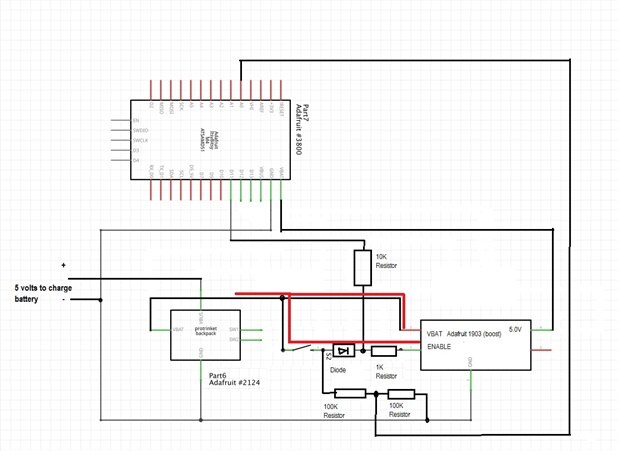
    OK, let's break this down just a bit.  In the first image, the switch is pressed and current flows (lower RED path) through the switch to the 'ENABLE' on the boost board (or regulator).  This applies power to the ItsyBitsy. (also showing current path to the boost in RED)

    image

    Now, upon wakeup the ItsyBitys Turns D11 High to provide another current path (ORANGE) to the 'ENABLE' on the boost board (or regulator).  This acts as a 'keep power on' signal.

    image

    Now, when the switch is released and current quits flowing through the lower RED path, the ORANGE path holds the  power on.

    image

    Now it is possible to use the switch as a user interface function, by monitoring the voltage between the two 100K resistors on 'A0' pin of the ItsyBitsy.  When the 'ItsyBitsy' decides that the current should shut down, the ItsyBitsy it turns D11 Low to to the disable on the boost board (or regulator) and shut the circuit down.


    I have used this logic on a number of battery powered projects and I find it to work quite well.

    • Cancel
    • Vote Up +2 Vote Down
    • Sign in to reply
    • Verify Answer
    • Cancel
  • justphred
    0 justphred over 6 years ago in reply to dougw

    What about the timing of it all, using a MOSFET would still give me the same issue wouldn't it? when I let up on the switch the board will lose power, and thus not keep the MOSFET circuit closed. Or am I not understanding how a MOSFET works correctly?

    • Cancel
    • Vote Up +1 Vote Down
    • Sign in to reply
    • Verify Answer
    • Cancel
Reply
  • justphred
    0 justphred over 6 years ago in reply to dougw

    What about the timing of it all, using a MOSFET would still give me the same issue wouldn't it? when I let up on the switch the board will lose power, and thus not keep the MOSFET circuit closed. Or am I not understanding how a MOSFET works correctly?

    • Cancel
    • Vote Up +1 Vote Down
    • Sign in to reply
    • Verify Answer
    • Cancel
Children
  • genebren
    0 genebren over 6 years ago in reply to justphred

    Michael,


    It appears as if there is a pull-up resistor on the enable input.  You could add a 10K resistor to ground to pull the pin low when it is not being driven high.  (Note: in a quick read of the chip and board datasheets, I see no mention of a pull up on the enable.  I should check this again with glasses on in the morning).


    If you have a 10K resistor to try as a pull down.  It will interesting to see what happens.


    Gene

    • Cancel
    • Vote Up 0 Vote Down
    • Sign in to reply
    • Verify Answer
    • Cancel
  • justphred
    0 justphred over 6 years ago in reply to genebren

    Ok I have some circuits out in front of me and I'm seeing a problem.


    I have one of those voltage boosts wired up. With nothing going to the Enable pin, and as it sits it is sending current to the board. If I jumper enable to ground the circuit shuts off and stops sending power to the board.


    Is this Enable working differently than expected?

    • Cancel
    • Vote Up +1 Vote Down
    • Sign in to reply
    • Verify Answer
    • Cancel
  • justphred
    0 justphred over 6 years ago in reply to genebren

    Gene, you are my hero, and I greatly appreciate you breaking it down like this!

    • Cancel
    • Vote Up +1 Vote Down
    • Sign in to reply
    • Verify Answer
    • Cancel
  • justphred
    0 justphred over 6 years ago in reply to dougw

    Doug, I think its just my lack of understanding an experience with a FET.

    • Cancel
    • Vote Up 0 Vote Down
    • Sign in to reply
    • Verify Answer
    • Cancel
  • dougw
    0 dougw over 6 years ago in reply to justphred

    The FET circuit I posted above handles all your requirements as I perceive them. If there is a feature missing, please explain.

    • Cancel
    • Vote Up +1 Vote Down
    • Sign in to reply
    • Verify Answer
    • Cancel
  • genebren
    0 genebren over 6 years ago in reply to justphred

    Michael,


    In each of the examples that I shared with you, I solve the problem with the switch release removing power, by having the microprocessor hold the circuit on (i.e. keeping the regulator, or boost enabled).  This removes the need for timing circuits to keep the transistor and/or MOSFET turned on.


    OK, let's break this down just a bit.  In the first image, the switch is pressed and current flows (lower RED path) through the switch to the 'ENABLE' on the boost board (or regulator).  This applies power to the ItsyBitsy. (also showing current path to the boost in RED)

    image

    Now, upon wakeup the ItsyBitys Turns D11 High to provide another current path (ORANGE) to the 'ENABLE' on the boost board (or regulator).  This acts as a 'keep power on' signal.

    image

    Now, when the switch is released and current quits flowing through the lower RED path, the ORANGE path holds the  power on.

    image

    Now it is possible to use the switch as a user interface function, by monitoring the voltage between the two 100K resistors on 'A0' pin of the ItsyBitsy.  When the 'ItsyBitsy' decides that the current should shut down, the ItsyBitsy it turns D11 Low to to the disable on the boost board (or regulator) and shut the circuit down.


    I have used this logic on a number of battery powered projects and I find it to work quite well.

    • Cancel
    • Vote Up +2 Vote Down
    • Sign in to reply
    • Verify Answer
    • Cancel
element14 Community

element14 is the first online community specifically for engineers. Connect with your peers and get expert answers to your questions.

  • Members
  • Learn
  • Technologies
  • Challenges & Projects
  • Products
  • Store
  • About Us
  • Feedback & Support
  • FAQs
  • Terms of Use
  • Privacy Policy
  • Legal and Copyright Notices
  • Sitemap
  • Cookies

An Avnet Company © 2026 Premier Farnell Limited. All Rights Reserved.

Premier Farnell Ltd, registered in England and Wales (no 00876412), registered office: Farnell House, Forge Lane, Leeds LS12 2NE.

Follow element14

  • X
  • Facebook
  • linkedin
  • YouTube