Once you have defined the Renesaspart with its multi function pins I'll be interested to see how you choose the function in the design
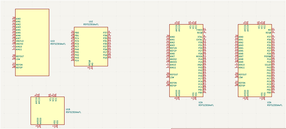
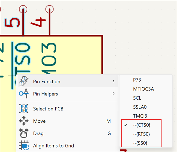
The 2 right ones in the image above are instances of my original "all pins" symbol for that same controller. You can spot that some pins (e.g.: pin 6 and 8) have a different function on U2 and U3. If you right-click on a multi-function pin, the menu will show the option "pin function":
Once you placed a symbol, you can right-click on it and select "Edit with symbol editor". You can then move pins around, for that particular instance on your schematic. Without affecting the library symbol.
I don't know if you can "slice and dice" an existing symbol into multiple units, once it's placed on a schema ... I haven't tried to do it, maybe it's easy ...
I don't know if you can "slice and dice" an existing symbol into multiple units, once it's placed on a schema ...
It is doable, but seems to have side effects.
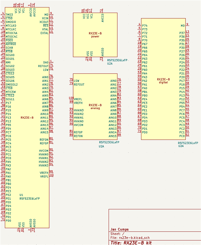
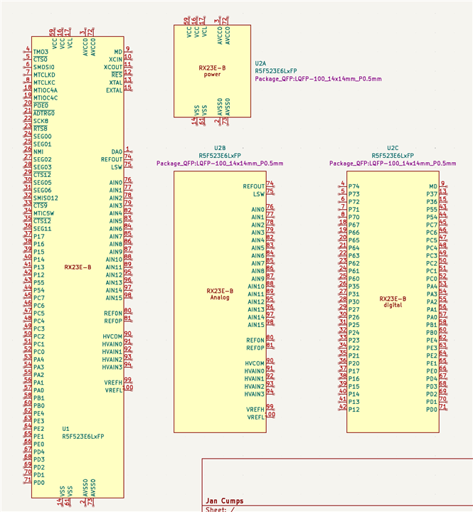
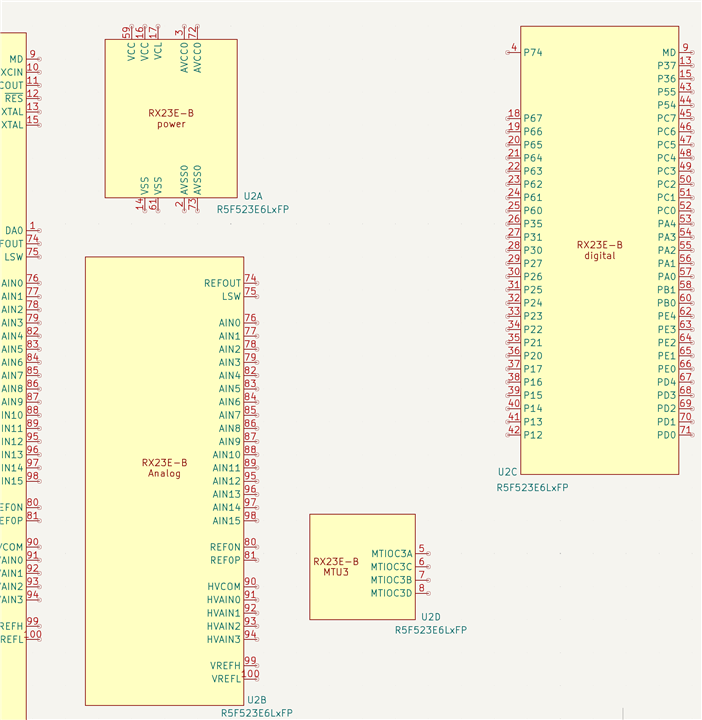
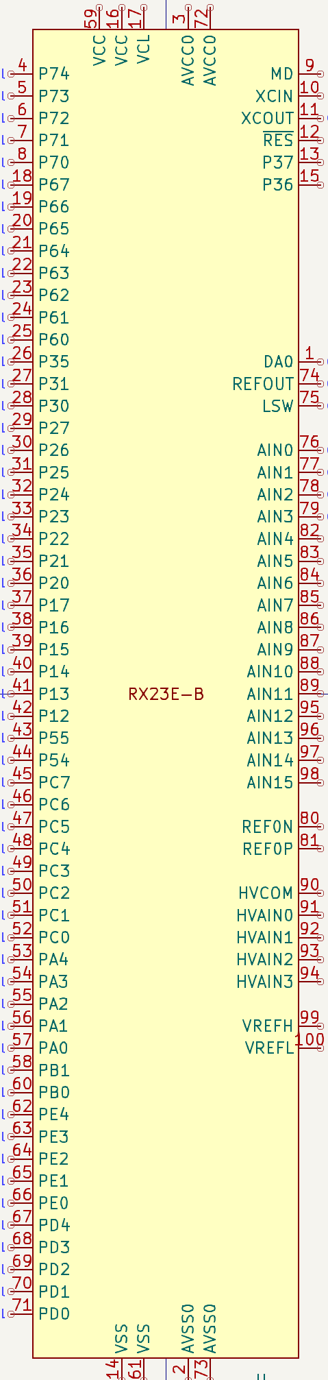
Below you see my full-pinned symbol. I duplicated it on the board, as U2.
Then I used the Symbol Editor on U2, and created 3 units, for this instance of the symbol only.
I was expecting that the schema editor then allows to place unit B and C, but it didn't.
I was able to create the image above by duplicateing U2 2 times, named all 3 U2, and then selected unit A, B and C. I'm sure that's not correct. If I ask KiCad to number my component, it does not work correctly. And the ERC fails for the 3 with the same name.
More trials needed ...
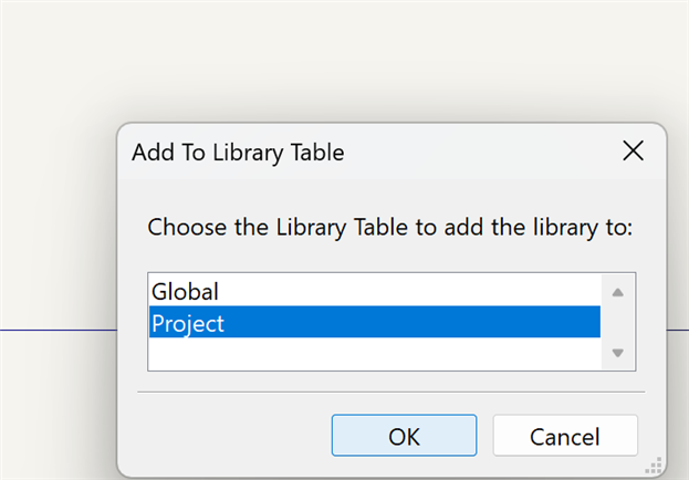
What I think would work is: copy the symbol into a project specific symbol library. Break that symbol up as needed by your project. Then place that one on the schematic. KiCAD would then prompt to place all units.
Thanks very much for the info. I'm not sure when I'll attempt a reasonable complex design with Kicad but I shall attempt to follow your tips when I do.
That's the correct link . That symbol lib contains two symbol versions of a 48-pin RX23E-A and the symbol of the 100-pin RX23E-B. Updating the post ...
Weird. I see the symbol file MCU_RENESAS_R.kicad_sym does contain the FP variant when I peek at it in a text editor.
However, when I import that file using the Symbol Editor File->Import->Symbol, it only imports the FL (48-pin) variant. I didn't actually know you could have more than one symbol in a kicad_sym file (I've only ever saved one symbol per file). How do you import that file?