Looks like the behaviour is different depending on what you do in KiCAD. This works:
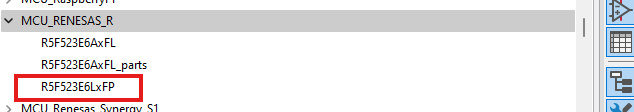
In library editor, select Add Library, then select if you want to add it to all (Global) or to the current project only. In essence, it just adds an entry to the library table, that points to the file.
From then on, all symbols are available:
I can also copy-paste the individual symbols now, between libraries. Makes sense if you add it to global, but want an independent copy in the local lib for your project.
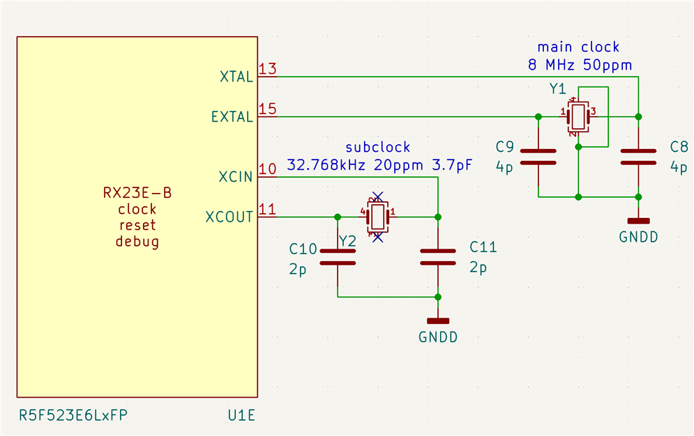
Where did the load caps come from? They look low in value to me.
If the 32.768kHz xtal is cut for 3.7pF, then assuming a pin/track value of something like 1.5pF (if you keep it compact and close to the pins), 5.6pF might work better. (5.6pF+1.5pF)/2 = 3.55pF
How curious. It would still work (it would probably work without any load caps and just the pin capacitance), but it would be a bit skittish and the RTC isn't going to keep very good time.
If I manage to get the board designed (daytime job creeps into the nighttime at the moment), I can learn some more about properly designing the clock circuit ...
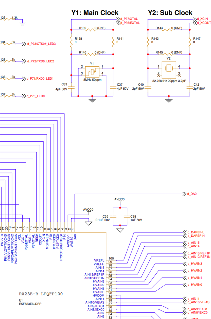
I'm making progress. The schematic is ready for anything that is not related to the analogue front end. I had to get that out of the way, before focusing on that part;
You don't have permission to edit metadata of this video.