element14 Community
element14 Community
    Register Log In
  • Site
  • Search
  • Log In Register
  • Community Hub
    Community Hub
    • What's New on element14
    • Feedback and Support
    • Benefits of Membership
    • Personal Blogs
    • Members Area
    • Achievement Levels
  • Learn
    Learn
    • Ask an Expert
    • eBooks
    • element14 presents
    • Learning Center
    • Tech Spotlight
    • STEM Academy
    • Webinars, Training and Events
    • Learning Groups
  • Technologies
    Technologies
    • 3D Printing
    • FPGA
    • Industrial Automation
    • Internet of Things
    • Power & Energy
    • Sensors
    • Technology Groups
  • Challenges & Projects
    Challenges & Projects
    • Design Challenges
    • element14 presents Projects
    • Project14
    • Arduino Projects
    • Raspberry Pi Projects
    • Project Groups
  • Products
    Products
    • Arduino
    • Avnet & Tria Boards Community
    • Dev Tools
    • Manufacturers
    • Multicomp Pro
    • Product Groups
    • Raspberry Pi
    • RoadTests & Reviews
  • About Us
  • Store
    Store
    • Visit Your Store
    • Choose another store...
      • Europe
      •  Austria (German)
      •  Belgium (Dutch, French)
      •  Bulgaria (Bulgarian)
      •  Czech Republic (Czech)
      •  Denmark (Danish)
      •  Estonia (Estonian)
      •  Finland (Finnish)
      •  France (French)
      •  Germany (German)
      •  Hungary (Hungarian)
      •  Ireland
      •  Israel
      •  Italy (Italian)
      •  Latvia (Latvian)
      •  
      •  Lithuania (Lithuanian)
      •  Netherlands (Dutch)
      •  Norway (Norwegian)
      •  Poland (Polish)
      •  Portugal (Portuguese)
      •  Romania (Romanian)
      •  Russia (Russian)
      •  Slovakia (Slovak)
      •  Slovenia (Slovenian)
      •  Spain (Spanish)
      •  Sweden (Swedish)
      •  Switzerland(German, French)
      •  Turkey (Turkish)
      •  United Kingdom
      • Asia Pacific
      •  Australia
      •  China
      •  Hong Kong
      •  India
      •  Korea (Korean)
      •  Malaysia
      •  New Zealand
      •  Philippines
      •  Singapore
      •  Taiwan
      •  Thailand (Thai)
      • Americas
      •  Brazil (Portuguese)
      •  Canada
      •  Mexico (Spanish)
      •  United States
      Can't find the country/region you're looking for? Visit our export site or find a local distributor.
  • Translate
  • Profile
  • Settings
Community Hub
Community Hub
Member's Forum Mains operated garage roller door position sensing mystery
  • Blog
  • Forum
  • Documents
  • Quiz
  • Events
  • Leaderboard
  • Polls
  • Files
  • Members
  • Mentions
  • Sub-Groups
  • Tags
  • More
  • Cancel
  • New
Join Community Hub to participate - click to join for free!
Actions
  • Share
  • More
  • Cancel
Forum Thread Details
  • Replies 10 replies
  • Subscribers 551 subscribers
  • Views 866 views
  • Users 0 members are here
Related

Mains operated garage roller door position sensing mystery

davebullockmbe
davebullockmbe over 1 year ago

So I have been tasked to discover how a 'roller' garage door knows when it is fully UP or Down and it is mystifying me

So here's all the information I have on the roller door controller. (pictured)

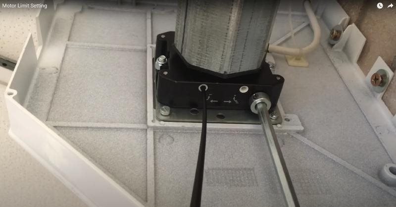
We took off the roller shutter cover inside the garage and all there is, is the skeleton roller mechanism with a square diecast looking housing that may be the motor connected to the roller at one end. 
The 4 core power cable goes into the diecast housing/body and after some searching the web I discovered that this is a 'tube motor' whose body is hidden inside the roller centre tube.
The diecast housing has a 'manual' winder loop sticking out of it with which one can manually wind the door up and down with a hooked handle, so the housing may just be gearbox and/or clutch?
So there are 4 wires going to the motor. (entering the diecast housing)
Earth, Neutral and two switched lives (UP and DOWN)
My internet trawl seems to show that the motor has two sets of 240V windings in opposite arrangement to allow it to reverse.
As far as I can tell only one live wire is energised at a time. (one going up and the other for coming down).image
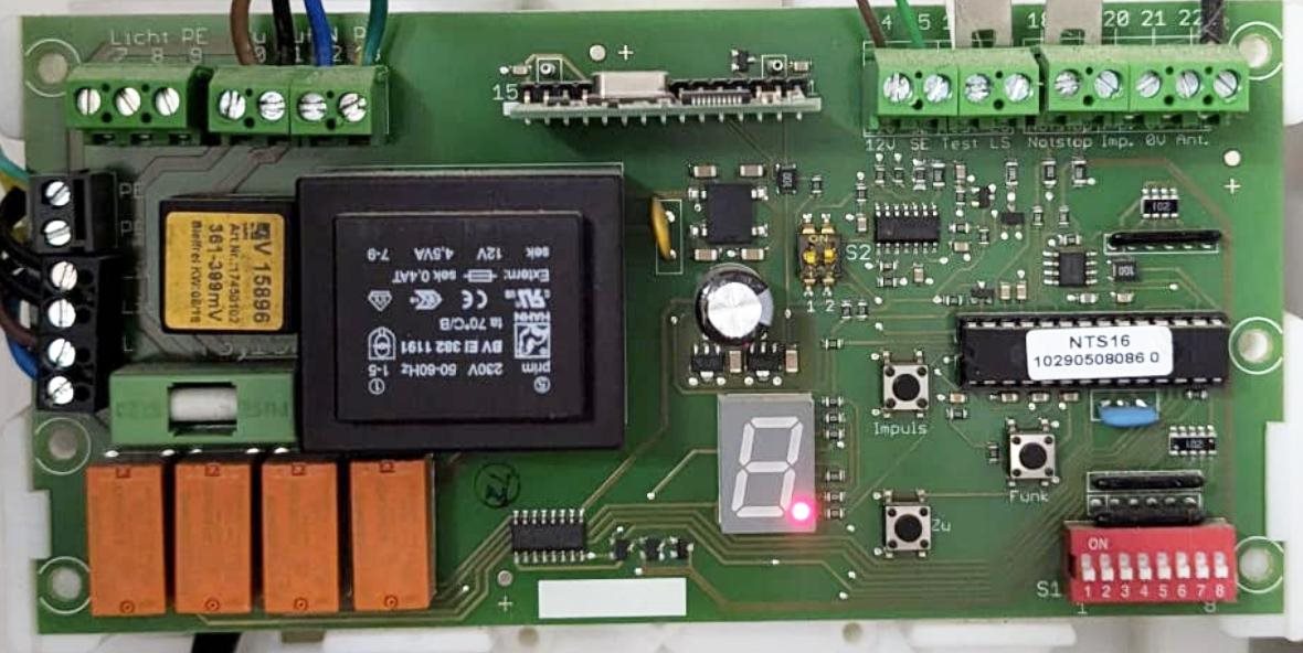
The up and down are controlled by two of those four orange relays bottom left on the controller pcb.
A third relay seems to disable all motor power, (or to make sure both up and down can't be on together?)
The fourth operates the lightbulb on top of the controller box!
All the relays seem to be driven via relay drivers directly from the microcontroller.
There are NO other wires coming from outside the controller other than the rubber pressure sensor at the bottom of the door.
Which does work!
So NO visible limit switches
No shaft encoders or extra wires from the motor housing etc.
So how does it know to stop at the top and bottom?
Could it be simply 'timing' based?
Well I don't think so as clearly IF the door ONLY went fully up and then fully down then this may be feasible.
However one can stop the door anywhere and reverse it several times and it still doesn't lose its sense of fully up or down or where it is!
Also It can't use the pressure sensor as yes this would work for fully down, but what about fully at the top?
Current sensing?
Well we tried monitoring the running current and it was 1.4A a.c. and this didn't seem to increase when the door hit the floor. However this was with a DVM which may not have been quick enough)
Will take my AVOmeter next time.
A (I don't know which) relay clicks OFF just after the door is fully closed, but the sequence is - it closes, all the slats squeeze up and then a relay can be heard to click and stops the motor.
There doesn't seem to be any evidence of current sensing wire shunts (at least on the face of the pcb) which detracts from the current sensing theory. But there could be something on the back of the board.
I may have to strip it out to investigate further but before I dismantle the whole thing someone just may save me a whole lot of investigation by knowing the secret and would kindly share the 'spell'?
Thanks in anticipation
Dave
  • Sign in to reply
  • Cancel

Top Replies

  • davebullockmbe
    davebullockmbe over 1 year ago in reply to javagoza +2
    Hi and a BIG thank-you to all respondents the mystery is solved. Whilst I was fully expecting any 'end of travel' limits to be relayed back to the controller, and the total lack of any evidence of limit…
  • kmikemoo
    kmikemoo over 1 year ago +1
    davebullockmbe This video will probably help. https://www.youtube.com/watch?v=Oii3L1Uw_XU Looks like he could use a few likes. 2:10 to 2:50 Not a bad teardown video.
  • shabaz
    shabaz over 1 year ago in reply to electronicbiker +1
    That thing with the yellow label on it is probably a current transformer, since as you suggest, overcurent protection would be needed anyway. It also looks like the fat traces pass through there, adding…
Parents
  • acdc90
    acdc90 over 1 year ago

    what model and brand is this machine, is  the board near the motor and maybe there is a hall effect sensor on back of board.

    what about a photo of whole assembly and back of board and looking where the board sits.   

    • Cancel
    • Vote Up 0 Vote Down
    • Sign in to reply
    • Cancel
  • davebullockmbe
    davebullockmbe over 1 year ago in reply to acdc90

    HI thanks for your thoughts so far.

    Yes I have thought of 'carefully' trying to stall the roller half way down to see if it stops proving that there is some sort of current sensing.

    I too spotted the mystery yellow labelled block with its mV range and wondered if this was a current transformer.

    I also wondered about putting a diode in series with the motor supply to slow it down to disprove any 'timing' method of knowing where it is. But I think I have disproved this theory anyway.

    The front cover is missing so there is no manufacturers information as to make or model ,although the roller itself has the name Novoferm emblazoned upon it.

    I will continue to investigate.

    Thanks

    Dave

    • Cancel
    • Vote Up 0 Vote Down
    • Sign in to reply
    • Cancel
  • javagoza
    javagoza over 1 year ago in reply to davebullockmbe

    I think Novoferm is a Spanish company. You can look for Novoport or Novomatic here: Documentación técnica | Novoferm (novofermalsal.com)

    Several Novoport versions share that layout

    image

    • Cancel
    • Vote Up 0 Vote Down
    • Sign in to reply
    • Cancel
  • davebullockmbe
    davebullockmbe over 1 year ago in reply to javagoza

    Hi and a BIG thank-you to all respondents the mystery is solved.

    Whilst I was fully expecting any 'end of travel' limits to be relayed back to the controller, and the total lack of any evidence of limit switches on the roller mechanism I was baffled.
    However the diecast box at one end of the roller was the magical answer.

    The black box shown in the attached picture on the roller I have been musing over, was a silver (unpainted) box and the two white adjusters are black. Consequently they just looked like blank holes in the darkness of the garage roof. There are no printed arrows like in the pictured item.
    The limit switches are concealed within the box and simply break the mains feed when the limit is reached. 
    I had no access to paperwork or any instructions until aided by your kind comments whereby I was able to search and actually find a YouTube video explaining how to adjust the 'said' limits.
    So simple once you know the secret.
    I am still wondering why the relay on the controller pcb clicks off after the door stops (rather than instantly) but this may still involve what looks like the yellow labelled (current?) transformer which would kind of make sense?

    Whatever, maybe a case of 'not seeing the wood for the trees' the mystery is solved as far as my involvement is concerned.

    Thank you all for your support and encouragement, "True community spirit"

    Dave

    image

    • Cancel
    • Vote Up +2 Vote Down
    • Sign in to reply
    • Cancel
  • Cquk
    Cquk over 1 year ago in reply to davebullockmbe

    Hi Just a note to say I work with a lot of these motors in electric blinds.

    Normally the control box is dumb. It just activates the relay for a timed period. As you corrently found out the limits are within the motor. This is normally done for safty.

    Quite often there is a current sensor in the control box so that if the motor is jamed it will kill the power. I expect in your case the limit switch kills the motor and then the controller then becomes open circit lead to its protection system releasing the relay. 

    We we install these motors we just have a toggle switch to send them up and down. No controll needed if this helps.

    JT

    • Cancel
    • Vote Up 0 Vote Down
    • Sign in to reply
    • Cancel
Reply
  • Cquk
    Cquk over 1 year ago in reply to davebullockmbe

    Hi Just a note to say I work with a lot of these motors in electric blinds.

    Normally the control box is dumb. It just activates the relay for a timed period. As you corrently found out the limits are within the motor. This is normally done for safty.

    Quite often there is a current sensor in the control box so that if the motor is jamed it will kill the power. I expect in your case the limit switch kills the motor and then the controller then becomes open circit lead to its protection system releasing the relay. 

    We we install these motors we just have a toggle switch to send them up and down. No controll needed if this helps.

    JT

    • Cancel
    • Vote Up 0 Vote Down
    • Sign in to reply
    • Cancel
Children
No Data
element14 Community

element14 is the first online community specifically for engineers. Connect with your peers and get expert answers to your questions.

  • Members
  • Learn
  • Technologies
  • Challenges & Projects
  • Products
  • Store
  • About Us
  • Feedback & Support
  • FAQs
  • Terms of Use
  • Privacy Policy
  • Legal and Copyright Notices
  • Sitemap
  • Cookies

An Avnet Company © 2025 Premier Farnell Limited. All Rights Reserved.

Premier Farnell Ltd, registered in England and Wales (no 00876412), registered office: Farnell House, Forge Lane, Leeds LS12 2NE.

ICP 备案号 10220084.

Follow element14

  • X
  • Facebook
  • linkedin
  • YouTube