element14 Community
element14 Community
    Register Log In
  • Site
  • Search
  • Log In Register
  • Community Hub
    Community Hub
    • What's New on element14
    • Feedback and Support
    • Benefits of Membership
    • Personal Blogs
    • Members Area
    • Achievement Levels
  • Learn
    Learn
    • Ask an Expert
    • eBooks
    • element14 presents
    • Learning Center
    • Tech Spotlight
    • STEM Academy
    • Webinars, Training and Events
    • Learning Groups
  • Technologies
    Technologies
    • 3D Printing
    • FPGA
    • Industrial Automation
    • Internet of Things
    • Power & Energy
    • Sensors
    • Technology Groups
  • Challenges & Projects
    Challenges & Projects
    • Design Challenges
    • element14 presents Projects
    • Project14
    • Arduino Projects
    • Raspberry Pi Projects
    • Project Groups
  • Products
    Products
    • Arduino
    • Avnet Boards Community
    • Dev Tools
    • Manufacturers
    • Multicomp Pro
    • Product Groups
    • Raspberry Pi
    • RoadTests & Reviews
  • Store
    Store
    • Visit Your Store
    • Choose another store...
      • Europe
      •  Austria (German)
      •  Belgium (Dutch, French)
      •  Bulgaria (Bulgarian)
      •  Czech Republic (Czech)
      •  Denmark (Danish)
      •  Estonia (Estonian)
      •  Finland (Finnish)
      •  France (French)
      •  Germany (German)
      •  Hungary (Hungarian)
      •  Ireland
      •  Israel
      •  Italy (Italian)
      •  Latvia (Latvian)
      •  
      •  Lithuania (Lithuanian)
      •  Netherlands (Dutch)
      •  Norway (Norwegian)
      •  Poland (Polish)
      •  Portugal (Portuguese)
      •  Romania (Romanian)
      •  Russia (Russian)
      •  Slovakia (Slovak)
      •  Slovenia (Slovenian)
      •  Spain (Spanish)
      •  Sweden (Swedish)
      •  Switzerland(German, French)
      •  Turkey (Turkish)
      •  United Kingdom
      • Asia Pacific
      •  Australia
      •  China
      •  Hong Kong
      •  India
      •  Korea (Korean)
      •  Malaysia
      •  New Zealand
      •  Philippines
      •  Singapore
      •  Taiwan
      •  Thailand (Thai)
      • Americas
      •  Brazil (Portuguese)
      •  Canada
      •  Mexico (Spanish)
      •  United States
      Can't find the country/region you're looking for? Visit our export site or find a local distributor.
  • Translate
  • Profile
  • Settings
Community Hub
Community Hub
Member's Forum Unexpected voltage at base of transistor?
  • Blog
  • Forum
  • Documents
  • Quiz
  • Events
  • Leaderboard
  • Polls
  • Files
  • Members
  • Mentions
  • Sub-Groups
  • Tags
  • More
  • Cancel
  • New
Join Community Hub to participate - click to join for free!
Actions
  • Share
  • More
  • Cancel
Forum Thread Details
  • Replies 9 replies
  • Subscribers 507 subscribers
  • Views 503 views
  • Users 0 members are here
Related

Unexpected voltage at base of transistor?

Sean_Miller
Sean_Miller over 6 years ago

I have a situation I hadn't encountered before that is really bringing out my inner "noob".  Below is a circuit I'm developing for one of my 4D Game Engine IoT devices (future Element14 Presents video).


The simple question is - would one expect to see a voltage at an open base of a transistor?


Here's the details:

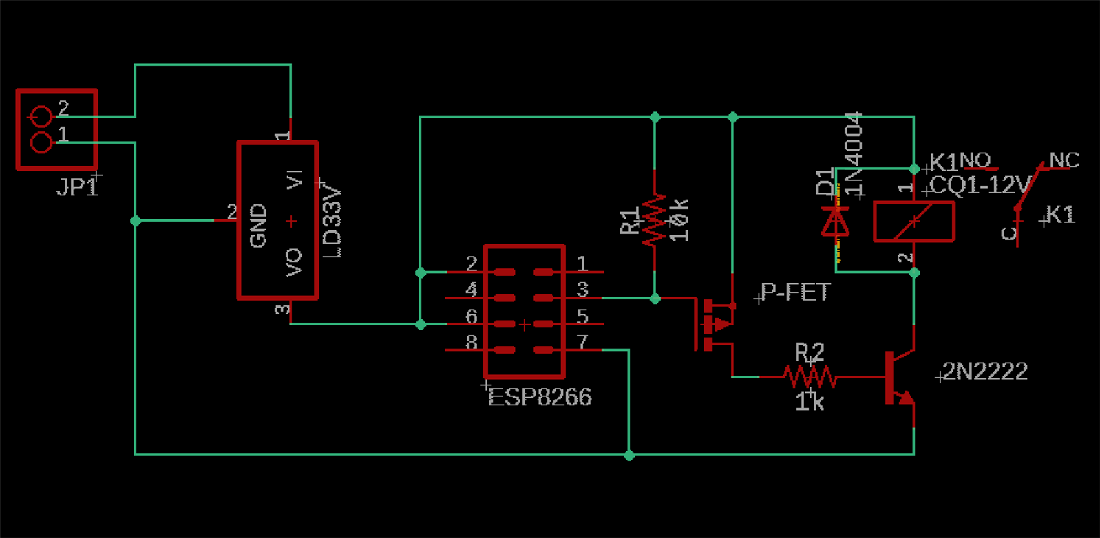
The SV1 is a 2x4 female header to plug in a ESP8266.  JP1 receives a 9V battery.  IC1 and IC2 are regulating down to 5Vs and then to 3.3V.


With the ESP8266 not installed, I probe pin three (the transistor base) to ground, I get 1.5 volts.  For that pin, if the ESP8266 sees voltage on power on, it will enter its bootloader mode.  In turn, its made the pin not an option to trigger the transistor because the voltage is instantly there when powered on and the circuit will be "bricked".


Is it normal to see a voltage on an base?  I rebuilt the board from scratch and breadboarded it just to ensure it wasn't a short, but the problem persisted.  I also added a 10K at the base hoping to "pull it down", but it did nothing for it.


image


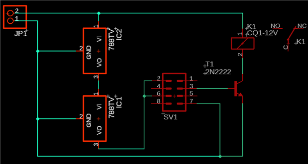
My solution, of course, was to use another pin, but I sure would like to have that one for other projects in the future.


Thanks,

Sean

  • Sign in to reply
  • Cancel

Top Replies

  • shabaz
    shabaz over 6 years ago in reply to Sean_Miller +2
    Hi Sean, You might be hitting this known bug: Test - JPG - Please Ignore The symptom is that the image appears for you, but not for others. The workaround is to subsequently edit the discussion/blog (even…
  • Sean_Miller
    Sean_Miller over 6 years ago in reply to jw0752 +2
    After a couple more hours of research, I found that other's come to the conclusion that the ESP8266 just isn't transistor friendly - this includes using an optocoupler because its LED circuit is still…
  • dougw
    dougw over 6 years ago +2
    If I'm reading it right, the 10K base resistor you tried should have pulled the base right to ground. If there is 1.5V on the base there is something very wrong - as in blown transistor - the base should…
  • jw0752
    jw0752 over 6 years ago

    Hi Sean,

    You will have to repost your illustration or schematic as it did not come through. Try using the icon for pictures in the header.

    John

    • Cancel
    • Vote Up +1 Vote Down
    • Sign in to reply
    • Cancel
  • Sean_Miller
    Sean_Miller over 6 years ago in reply to jw0752

    That is strange the picture isn't coming through.  I had used the icon and it shows on my end.


    However, I believe I figured it out.  I'm mistaking what I'm seeing.  The transistor base is instead acting as a resistance to ground.  So it's like I'm probing a voltage divider circuit.


    So, the transistor is pulling the pin down.  The ESP8266 pins need to be pulled high to keep them out of boot mode when powered up.  So, the transistor in this circuit will always give me fits.  One document online talked about using an optocoupler which would simply be driving an LED inside the package which should work in theory.  I'll try that next. 


    Never thought I'd spend have >8 hours of probing & researching on one pin!!!  I guess that's what bakes it into the noodle, though.


    See ya',

    Sean

    • Cancel
    • Vote Up +1 Vote Down
    • Sign in to reply
    • Cancel
  • shabaz
    shabaz over 6 years ago in reply to Sean_Miller

    Hi Sean,


    You might be hitting this known bug:

    Test - JPG - Please Ignore

    The symptom is that the image appears for you, but not for others. The workaround is to subsequently edit the discussion/blog (even if it is just adding some space or carriage-returns on the end of the post) and then it fixes it : )

    • Cancel
    • Vote Up +2 Vote Down
    • Sign in to reply
    • Cancel
  • Sean_Miller
    Sean_Miller over 6 years ago in reply to jw0752

    After a couple more hours of research, I found that other's come to the conclusion that the ESP8266 just isn't transistor friendly - this includes using an optocoupler because its LED circuit is still enough to pull down the pin taking it to boot mode on powerup.  So, I put in a switch for now between the pin and transistor that allows me to at least get it going.


    -Sean

    • Cancel
    • Vote Up +2 Vote Down
    • Sign in to reply
    • Cancel
  • dougw
    dougw over 6 years ago

    If I'm reading it right, the 10K base resistor you tried should have pulled the base right to ground.

    If there is 1.5V on the base there is something very wrong - as in blown transistor - the base should not be able to exceed about 0.7V because the base-emitter diode will conduct above that voltage.

    If pin3 on SV1 is an output, the base can only be driven up to 0.7V so it needs a current limiting resistor between pin 3 and the base.

    I would use a FET like a BSS138 or a 2N7000 instead of the  2N22222N2222 where a high value resistor would be sufficient to pull the gate down

    A series base resistor will work with the  2N22222N2222 but you probably also want a pull down on the base to make sure the transistor is off when the base is floating

    • Cancel
    • Vote Up +2 Vote Down
    • Sign in to reply
    • Cancel
  • Sean_Miller
    Sean_Miller over 6 years ago in reply to dougw

    I realized my original sketch didn't show the resistor to the base, but had a 1K there.  However, I didn't have a flyback diode on the relay.  That could have been eating transistors on me.


    My 10K pull down resistor was totally backwards thinking for my problem.  What I needed was a pull up which a lot of people have said have worked for the ESP8266.  However, I could not get it to work.  The pull up resistor would simply trigger the transistor and keep it there despite what the code was doing.


    So here is the circuit now, but I will loop back to try your FET suggestion at some point as the switch solution is goofy.

    image


    Thanks for the help!

    Sean

    • Cancel
    • Vote Up +1 Vote Down
    • Sign in to reply
    • Cancel
  • Sean_Miller
    Sean_Miller over 6 years ago in reply to dougw

    Ok...Got the FET installed and now all is well!


    I needed at least 5V to get the relay to pull in so I used the FET at 3.3V to switch a  2N22222N2222 transistor This arrangement isolated pin 3 from being pulled down at boot up allowing an added 10K pull up resistor to keep the pin high allowing it to boot to my flashed code So now this IoT circuit can switch on AC or DC appliances over the web running on a battery or power source anywhere from 5V-15V DC


    image


    The board turned out pretty sleek:


    With ESP8266:

    image


    With ESP8266 removed:

    image


    See ya',

    Sean

    • Cancel
    • Vote Up +2 Vote Down
    • Sign in to reply
    • Cancel
  • Gough Lui
    Gough Lui over 6 years ago in reply to Sean_Miller

    A bit late to the party myself - but I'm not sure if you're aware of these cheap boards on eBay:

    https://www.ebay.com.au/itm/5V-ESP8266-ESP-01S-Relay-Module-Remote-Switch-Phone-APP-DIY-Kit-Project-Design/282743533090?…


    Basically, an ESP-01 module, a relay, voltage regulator and a transistor and resistors on a PCB for AU$1.88. You can reprogram the ESP-01 to whatever you'd like and at that price, it's a lot of fun. Of course, I'm not discouraging people from designing their own and  learning in the process - but at that price, it's hard to want to deal with the headaches ... although delivery is often a bit of an issue with goods sourced from China as it can take forever and incur some customs duties.


    - Gough


    EDIT: Actually the one above doesn't include the ESP-01 module itself.

    https://www.ebay.com.au/itm/ESP8266-ESP-01S-5V-Wifi-Relay-Module-TOI-APP-Controled-For-Smart-Home/282649817635?hash=item…

    The one with the module is about AU$4.06. Still absurdly cheap if you ask me image. I've actually got a few of these on hand but haven't had the chance to put it into good use yet.

    • Cancel
    • Vote Up 0 Vote Down
    • Sign in to reply
    • Cancel
  • Sean_Miller
    Sean_Miller over 6 years ago in reply to Gough Lui

    Thanks for linking.  I have seen these.  Ebay definitely has some good gizmos at a fair price out there.  However, I recently got burned on a power supply that claimed to be good for 40V to step down to 3.3V, though.  It shorted through and toasted my MRK1000.


    My current obsessions are a bit retro.  I want to understand the analog world as best as I can while growing my code & circuit design blocks to later build bigger single boards for our projects.


    See ya',

    Sean

    • Cancel
    • Vote Up 0 Vote Down
    • Sign in to reply
    • Cancel
element14 Community

element14 is the first online community specifically for engineers. Connect with your peers and get expert answers to your questions.

  • Members
  • Learn
  • Technologies
  • Challenges & Projects
  • Products
  • Store
  • About Us
  • Feedback & Support
  • FAQs
  • Terms of Use
  • Privacy Policy
  • Legal and Copyright Notices
  • Sitemap
  • Cookies

An Avnet Company © 2025 Premier Farnell Limited. All Rights Reserved.

Premier Farnell Ltd, registered in England and Wales (no 00876412), registered office: Farnell House, Forge Lane, Leeds LS12 2NE.

ICP 备案号 10220084.

Follow element14

  • X
  • Facebook
  • linkedin
  • YouTube