


After experimenting with the V2DIP1-48V2DIP1-48 from FTDI connecting over SPI, SPI Slave on an Arduino MKR Zero, I wasn't sure if the Arduino code or the FTDI firmware was the problem. After some more experiments I concluded that there was definitely something up with the firmware.
Reading one of the examples, I spotted the following gem:
This sample has been designed for the V2Eval Board Rev 2.0 and later. V2Eval Boards have the version printed on the silk screen next to the V2EVAL label.
The V2Eval boards Rev 1 require a different IOMux setting for this sample to function.
My board was labelled Rev1.1 so hence it could be that my I/O multiplexer configuration was the issue.
Hardware
I had previously tried the UART mechanism for compiling the code and sending to the board. FTDI Loading a ROM over UART? Perhaps this also a pin mapping issue?
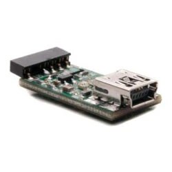
This had not been working but when I used the official debugger it was fine. The debugger needs a USB miniB cable and simply plugs into the back of the V2DIP1-48V2DIP1-48 device then works with the FT_PROG application or the IDE.
Tool Chain
The first step on getting to blink is to install the tools. https://www.ftdichip.com/Firmware/VNC2tools.htm
There's a simple IDE called "Vinculumn II IDE" and you can compile the code from there. There are also some wizards and one that on first impressions looks like it should help the issue with multiplexing, you pick the target board then select a pin to configure it. You can see which pins and signals you can choose from.


It generates some code for the multiplexer configuration based on the pins you pick in the diagram, so I picked IO5 and IO6 as I knew they were hooked up to the two green LEDs.
I ran the code up in the debugger and confirmed that my device was indeed being recognised as a 48 pin variant. Note that you can create the code for the other two versions too.
But this didn't seem to work.
packageType = vos_get_package_type();
if (packageType == VINCULUM_II_48_PIN)
{
// GPIO_Port_A_1 to pin 22 as Input.
vos_iomux_define_input(22, IOMUX_IN_GPIO_PORT_A_1);
// GPIO_Port_A_2 to pin 24 as Input.
vos_iomux_define_input(24, IOMUX_IN_GPIO_PORT_A_2);
If we look at the schematic for the schematic for the V2DIP1-48V2DIP1-48 IO5 is actually on pin 16 and IO6 is pin 18, not 22 and 24.
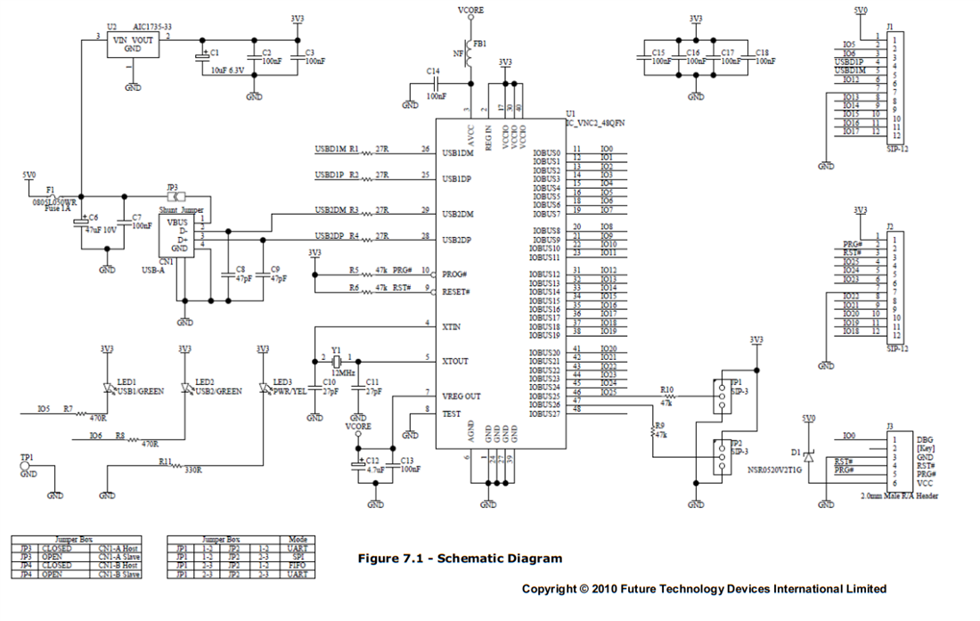
So I adjusted the mapping as follows:
// GPIO_Port_A_1 to pin 16 IO5 as Output
vos_iomux_define_output(16, IOMUX_OUT_GPIO_PORT_A_1);
// GPIO_Port_A_2 to pin 18 IO6 as Output
vos_iomux_define_output(18, IOMUX_OUT_GPIO_PORT_A_2);
No delay
There is no delay function in the library but there is vos_delay_msecs. I tried this in a simple loop and nothing happened. Looking at the docs in more detail, you can only use this if you scheduled a new thread.
So our final blink app looks as follows.
/*
** Filename: Blink.c
**
** Automatically created by Application Wizard 2.0.2
**
** Part of solution Blink in project Blink
**
** Comments:
**
** Important: Sections between markers "FTDI:S*" and "FTDI:E*" will be overwritten by
** the Application Wizard
*/

#include "Blink.h"

vos_tcb_t *tcbBlinkApp;

VOS_HANDLE hGPIO_PORT_A; // GPIO Port A Driver

void blinkApp()
{
while(1 == 1) {
    vos_gpio_write_pin(GPIO_A_1, 1);
    vos_gpio_write_pin(GPIO_A_2, 1);

    vos_delay_msecs(500);

    vos_gpio_write_pin(GPIO_A_1, 0);
    vos_gpio_write_pin(GPIO_A_2, 0);

    vos_delay_msecs(500);
    }
}

/* Main code - entry point to firmware */
void main(void)
{

// GPIO Port A configuration context
gpio_context_t gpioContextA;

/* FTDI:SKI Kernel Initialisation */
vos_init(50, VOS_TICK_INTERVAL, VOS_NUMBER_DEVICES);
vos_set_clock_frequency(VOS_48MHZ_CLOCK_FREQUENCY);
vos_set_idle_thread_tcb_size(512);
/* FTDI:EKI */

// Imported from iomux to simplify the code
// GPIO_Port_A_1 to pin 16 as Output.
vos_iomux_define_output(16, IOMUX_OUT_GPIO_PORT_A_1);
// GPIO_Port_A_2 to pin 18 as Output.
vos_iomux_define_output(18, IOMUX_OUT_GPIO_PORT_A_2);

// Initialise GPIO B
gpioContextA.port_identifier = GPIO_PORT_A;
gpio_init(VOS_DEV_GPIO_PORT_A,&gpioContextA);

vos_gpio_set_pin_mode(GPIO_A_1,1);
vos_gpio_set_pin_mode(GPIO_A_2,1);


/* FTDI:SCT Thread Creation */
tcbBlinkApp = vos_create_thread_ex(20, 4096, blinkApp, "Application", 0);
/* FTDI:ECT */

vos_start_scheduler();

main_loop:
    goto main_loop;
}
And now the green LEDs flashes as expected.
So next up, recompile the Uart/SPI firmware with some pins that are connected to the module and I'll try again to get it to work.
Some additional reference, this chip is described in Nuts and Volts Magazine September 2011. https://nutsvolts.texterity.com/nutsvolts/201109?pg=68#pg68
And describes the bigger development board the "Vinco 101" which a lot of the examples seem to be written for.

Top Comments
-

Workshopshed
-
Cancel
-
Vote Up
+2
Vote Down
-
-
Sign in to reply
-
More
-
Cancel
Comment-

Workshopshed
-
Cancel
-
Vote Up
+2
Vote Down
-
-
Sign in to reply
-
More
-
Cancel
Children