element14 Community
element14 Community
    Register Log In
  • Site
  • Search
  • Log In Register
  • Community Hub
    Community Hub
    • What's New on element14
    • Feedback and Support
    • Benefits of Membership
    • Personal Blogs
    • Members Area
    • Achievement Levels
  • Learn
    Learn
    • Ask an Expert
    • eBooks
    • element14 presents
    • Learning Center
    • Tech Spotlight
    • STEM Academy
    • Webinars, Training and Events
    • Learning Groups
  • Technologies
    Technologies
    • 3D Printing
    • FPGA
    • Industrial Automation
    • Internet of Things
    • Power & Energy
    • Sensors
    • Technology Groups
  • Challenges & Projects
    Challenges & Projects
    • Design Challenges
    • element14 presents Projects
    • Project14
    • Arduino Projects
    • Raspberry Pi Projects
    • Project Groups
  • Products
    Products
    • Arduino
    • Avnet & Tria Boards Community
    • Dev Tools
    • Manufacturers
    • Multicomp Pro
    • Product Groups
    • Raspberry Pi
    • RoadTests & Reviews
  • About Us
  • Store
    Store
    • Visit Your Store
    • Choose another store...
      • Europe
      •  Austria (German)
      •  Belgium (Dutch, French)
      •  Bulgaria (Bulgarian)
      •  Czech Republic (Czech)
      •  Denmark (Danish)
      •  Estonia (Estonian)
      •  Finland (Finnish)
      •  France (French)
      •  Germany (German)
      •  Hungary (Hungarian)
      •  Ireland
      •  Israel
      •  Italy (Italian)
      •  Latvia (Latvian)
      •  
      •  Lithuania (Lithuanian)
      •  Netherlands (Dutch)
      •  Norway (Norwegian)
      •  Poland (Polish)
      •  Portugal (Portuguese)
      •  Romania (Romanian)
      •  Russia (Russian)
      •  Slovakia (Slovak)
      •  Slovenia (Slovenian)
      •  Spain (Spanish)
      •  Sweden (Swedish)
      •  Switzerland(German, French)
      •  Turkey (Turkish)
      •  United Kingdom
      • Asia Pacific
      •  Australia
      •  China
      •  Hong Kong
      •  India
      •  Korea (Korean)
      •  Malaysia
      •  New Zealand
      •  Philippines
      •  Singapore
      •  Taiwan
      •  Thailand (Thai)
      • Americas
      •  Brazil (Portuguese)
      •  Canada
      •  Mexico (Spanish)
      •  United States
      Can't find the country/region you're looking for? Visit our export site or find a local distributor.
  • Translate
  • Profile
  • Settings
Personal Blogs
  • Community Hub
  • More
Personal Blogs
Legacy Personal Blogs Current Sensor 1. Introduction.
  • Blog
  • Documents
  • Mentions
  • Sub-Groups
  • Tags
  • More
  • Cancel
  • New
  • Share
  • More
  • Cancel
Group Actions
  • Group RSS
  • More
  • Cancel
Engagement
  • Author Author: peterjcs23
  • Date Created: 21 Feb 2015 5:26 PM Date Created
  • Views 2988 views
  • Likes 7 likes
  • Comments 18 comments
  • rogowski
  • current
  • hall-effect
  • know-how
  • shunt
  • hall
  • electronics
  • analog
  • sensor
Related
Recommended

Current Sensor 1. Introduction.

peterjcs23
peterjcs23
21 Feb 2015

Current Sensor 1. Introduction.


19 Feb 2015


Voltage and current sensing are fundamental to electrical and electronic circuits. Pretty much all analogue parametric sensors have a voltage output that is going to be compatible with the input of some measuring device, for example an ADC or the input to an amplifier. Current sensors must in some way convert the current to voltage for measurement and in general there are 2 methods, either a resistor is in the current path and the voltage across the resistor is measured, or the magnetic field around the current path is detected and converted to voltage for measurement. In the photograph at the heading of this blog both types of current sensor are represented.


Current sensing is required in a wide range of electrical and electronic applications. For example:

  • Battery life indicators and chargers
  • Over-current protection
  • Current and voltage  regulators
  • Power supply controllers
  • Current control in solenoids
  • Motor torque control
  • Heater controls
  • And so on


The current may range from milliamps to thousands of amps, it may be DC or AC, it may be steady or transient.


Direct current sensing – resistive - invasive.


Direct resistive current sensing is based on Ohm’s Law, by placing a resistor (perhaps referred to as a current shunt) in series with a load, a voltage is generated that is proportional to the current. The voltage may be scaled by an amplifier before it is passed to the measurement circuit. The amplifier may be a specialist current shunt monitor, an operational amplifier, a difference amplifier or an instrumentation amplifier. This method of measurement is referred to as invasive, there is no galvanic isolation, as the current shunt resistor and measurement circuit are connected to the circuit whose parameters are being measured; so grounding and common mode voltage must be considered when such a measurement is made. If galvanic isolation is required with a current shunt then an isolation amplifier must be used. The current shunt resistor will dissipate heat as I2R and the value of R used will be determined by the allowed heating effect traded off with the sensing voltage range and the amplifier gain.


Indirect current sensing – magnetic field – isolated.


Indirect current sensing is based on Ampere’s and Faraday’s laws of magnetism. There are a number of configurations for the sensing element relative to the current carrying conductor. If a toroid magnetic material is wrapped around the conductor and a slot is cut in it, then the magnetic field in the resulting air gap is proportional to the current in the conductor. The magnetic field must be converted to a voltage in order to measure it and a Hall Effect sensor is often used. This type of sensor has no direct connection to the circuit that carries the current and is therefore isolated or non-invasive. In a variant of this method, the toroid may have a secondary coil wound onto it and a current passed through the coil such that it opposes the field of the conductor we wish to measure. In this case, a closed loop circuit sets the secondary current to achieve zero field in the air gap; the secondary current is proportional to the primary current and can be measured by a current shunt; galvanic isolation still exists between the primary and secondary circuits.

Current transformers work with AC current by winding a large number of turns onto the secondary of the transformer core and the primary is a single turn passing through the core. The current in the secondary is measured by generating a voltage across a resistor but galvanic isolation is maintained between the measurement and primary circuits.

A Rogowski current sensor is an air cored coil where the coil is wrapped around the conductor. The voltage output of such a coil is proportional to the rate of change of current so an integrator is used to generate a voltage for the measurement circuit.


image


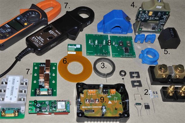
Types of current sensor:

  1. Typical current shunt resistor, 200A generates 50mV output.
  2. Current measurement resistor, 0.05R.
  3. Toroid made of silicon steel with a Hall Sensor in an air gap.
  4. Closed loop Hall Sensor, the secondary coil is wound on a ferrite core and potted.
  5. Current Transformer
  6. Rogowski coil made on a PCB with integrator and amplifier.
  7. These sensors all use a toroid, air gap and Hall sensor.
  8. These sensors use a magnetic core and Hall sensor miniaturised into a package with an amplifier.
  9. 20A current shunt in a DC electrical meter.

Also available at https://electronicsknowhowblog.wordpress.com/

  • Sign in to reply

Top Comments

  • shabaz
    shabaz over 9 years ago in reply to Former Member +2
    You can automate anything w.r.t. PCB designs. Write your code to generate a script file (.scr) which EAGLE can read, and it can contain any arbitrary lines with any arbitrary co-ordinates. Basically, express…
Parents
  • Former Member
    Former Member over 9 years ago

    I'm trying to replicate no. 6 Rogowski coil made on a PCB with integrator and amplifier as a project.

    But I'm stuck with getting a software that allows mt to 'wrap' traces on a pcb board that can be exported to gerber format.

    Anyone tried this before or have any suggestions how i can accomplish it?

    • Cancel
    • Vote Up 0 Vote Down
    • Sign in to reply
    • More
    • Cancel
Comment
  • Former Member
    Former Member over 9 years ago

    I'm trying to replicate no. 6 Rogowski coil made on a PCB with integrator and amplifier as a project.

    But I'm stuck with getting a software that allows mt to 'wrap' traces on a pcb board that can be exported to gerber format.

    Anyone tried this before or have any suggestions how i can accomplish it?

    • Cancel
    • Vote Up 0 Vote Down
    • Sign in to reply
    • More
    • Cancel
Children
  • peterjcs23
    peterjcs23 over 9 years ago in reply to Former Member

    'wrap' traces on a pcb board that can be exported to gerber format.


    I don't know of a PCB package that wraps coils. We set out the pattern of vias and joined them point to point.

    • Cancel
    • Vote Up 0 Vote Down
    • Sign in to reply
    • More
    • Cancel
  • Former Member
    Former Member over 9 years ago in reply to peterjcs23

    ok, I tried with Eagle, unfortunately it is not possible to automate the pattern.

    • Cancel
    • Vote Up 0 Vote Down
    • Sign in to reply
    • More
    • Cancel
  • shabaz
    shabaz over 9 years ago in reply to Former Member

    You can automate anything w.r.t. PCB designs. Write your code to generate a script file (.scr) which EAGLE can read, and it can contain any arbitrary lines with any arbitrary co-ordinates. Basically, express your design in a script file, or in code that can generate a script file. It might take some studying of how script files work, but it is certainly possible.

    • Cancel
    • Vote Up +2 Vote Down
    • Sign in to reply
    • More
    • Cancel
  • peterjcs23
    peterjcs23 over 9 years ago in reply to Former Member

    do you know what pattern you want to make? Put a sketch on the blog and perhaps shabaz or an Eagle expert can tell you what to do.

    • Cancel
    • Vote Up 0 Vote Down
    • Sign in to reply
    • More
    • Cancel
  • Former Member
    Former Member over 9 years ago in reply to peterjcs23

    Thanks Peter, I have posted it here: https://www.element14.com/community/message/165968/l/pcb-based-rogowski-coil-design-software#165968

    • Cancel
    • Vote Up 0 Vote Down
    • Sign in to reply
    • More
    • Cancel
element14 Community

element14 is the first online community specifically for engineers. Connect with your peers and get expert answers to your questions.

  • Members
  • Learn
  • Technologies
  • Challenges & Projects
  • Products
  • Store
  • About Us
  • Feedback & Support
  • FAQs
  • Terms of Use
  • Privacy Policy
  • Legal and Copyright Notices
  • Sitemap
  • Cookies

An Avnet Company © 2025 Premier Farnell Limited. All Rights Reserved.

Premier Farnell Ltd, registered in England and Wales (no 00876412), registered office: Farnell House, Forge Lane, Leeds LS12 2NE.

ICP 备案号 10220084.

Follow element14

  • X
  • Facebook
  • linkedin
  • YouTube