element14 Community
element14 Community
    Register Log In
  • Site
  • Search
  • Log In Register
  • Community Hub
    Community Hub
    • What's New on element14
    • Feedback and Support
    • Benefits of Membership
    • Personal Blogs
    • Members Area
    • Achievement Levels
  • Learn
    Learn
    • Ask an Expert
    • eBooks
    • element14 presents
    • Learning Center
    • Tech Spotlight
    • STEM Academy
    • Webinars, Training and Events
    • Learning Groups
  • Technologies
    Technologies
    • 3D Printing
    • FPGA
    • Industrial Automation
    • Internet of Things
    • Power & Energy
    • Sensors
    • Technology Groups
  • Challenges & Projects
    Challenges & Projects
    • Design Challenges
    • element14 presents Projects
    • Project14
    • Arduino Projects
    • Raspberry Pi Projects
    • Project Groups
  • Products
    Products
    • Arduino
    • Avnet & Tria Boards Community
    • Dev Tools
    • Manufacturers
    • Multicomp Pro
    • Product Groups
    • Raspberry Pi
    • RoadTests & Reviews
  • About Us
  • Store
    Store
    • Visit Your Store
    • Choose another store...
      • Europe
      •  Austria (German)
      •  Belgium (Dutch, French)
      •  Bulgaria (Bulgarian)
      •  Czech Republic (Czech)
      •  Denmark (Danish)
      •  Estonia (Estonian)
      •  Finland (Finnish)
      •  France (French)
      •  Germany (German)
      •  Hungary (Hungarian)
      •  Ireland
      •  Israel
      •  Italy (Italian)
      •  Latvia (Latvian)
      •  
      •  Lithuania (Lithuanian)
      •  Netherlands (Dutch)
      •  Norway (Norwegian)
      •  Poland (Polish)
      •  Portugal (Portuguese)
      •  Romania (Romanian)
      •  Russia (Russian)
      •  Slovakia (Slovak)
      •  Slovenia (Slovenian)
      •  Spain (Spanish)
      •  Sweden (Swedish)
      •  Switzerland(German, French)
      •  Turkey (Turkish)
      •  United Kingdom
      • Asia Pacific
      •  Australia
      •  China
      •  Hong Kong
      •  India
      • Japan
      •  Korea (Korean)
      •  Malaysia
      •  New Zealand
      •  Philippines
      •  Singapore
      •  Taiwan
      •  Thailand (Thai)
      • Vietnam
      • Americas
      •  Brazil (Portuguese)
      •  Canada
      •  Mexico (Spanish)
      •  United States
      Can't find the country/region you're looking for? Visit our export site or find a local distributor.
  • Translate
  • Profile
  • Settings
Personal Blogs
  • Community Hub
  • More
Personal Blogs
Legacy Personal Blogs My First Ever Crimping Experience
  • Blog
  • Documents
  • Mentions
  • Sub-Groups
  • Tags
  • More
  • Cancel
  • New
  • Share
  • More
  • Cancel
Group Actions
  • Group RSS
  • More
  • Cancel
Engagement
  • Author Author: dubbie
  • Date Created: 20 Nov 2020 2:54 PM Date Created
  • Views 5193 views
  • Likes 10 likes
  • Comments 34 comments
  • spade connections
  • crimping
Related
Recommended

My First Ever Crimping Experience

dubbie
dubbie
20 Nov 2020

For my Sand Based Cat Detector (Cat Detector Using Sand #2 : The Implementation ) I used a lead acid battery with spade connections. I have never properly used spade connections before (I usually use crocodile clips or solder directly) so I thought this would be a good time to start as I am working my way towards an outdoor mobile robot and robust and reliable connections are essential. Not really knowing much about making spade or crimping connections I decide that the best approach would be to buy some and just try it out. I have wanted to crimp for some time so rather than find out about it I just blundered in and bought something. I do not expect to do much crimping in the future so just looked online and bought the cheapest set I could find that seemed to do what I wanted.


You don't have permission to edit metadata of this video.
Edit media
x
image
Upload Preview
image


I used deep learning to update my natural neural networks in my head, basically I just stuck some wire inside the crimpets (or connectors) and tried to make good connections with the wire using the crimping tool. Initially there was little success as the tool I obtained did not come with any instructions what-so-ever. The crimpets would not stay on the wire while I attempted to use the crimping tool and several crimpets were harmed in this process.


image


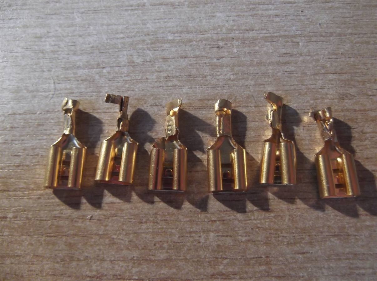
It took me several attempts to work out that the tool I had purchased did not do any folding of the little tabs on the crimpets. Once I had worked this out and folded over the ;little tabs using some pin nosed pliers I was able to make some good crimped connections. I'm not sure if it uses cold-welding or just mechanical interference to make a good physical and electrical connection, but they seem to work, so all is good.


Dubbie

  • Sign in to reply

Top Comments

  • shabaz
    shabaz over 5 years ago in reply to ajcc +8
    Hi Adrian, Probably everyone has their own recommendations, I've been quite impressed with the Multicomp HT-xxx range, I have several of them, they are about $25 ballpark. The HT-230 crimp tool HT-230…
  • shabaz
    shabaz over 5 years ago +7
    Hi Dubbie, I do the same as Doug, i.e. add some solder (after crimping) if the specific crimp tool isn't suitable. However, I think maybe your tool might do both the bare wire crimping and the insulation…
  • dougw
    dougw over 5 years ago +5
    There is a lot of science behind good crimp connections. I suspect they rely on the wire bring more springy than the crimp terminal, so after a crimp there is always force on the joint Whenever I don't…
Parents
  • shabaz
    shabaz over 5 years ago

    Hi Dubbie,


    I do the same as Doug, i.e. add some solder (after crimping) if the specific crimp tool isn't suitable. However, I think maybe your tool might do both the bare wire crimping and the insulation gripping in one go. The tool looks weird though, as if it is upside down. I think it needs to be held as shown, with the text on it upside-down, and the cable insulation held and fed in from the side with the text on it, with the terminal positioned as shown in the diagram below (apologies for the very crude diagram, hopefully it's clear). Also, although ideally nothing should be folded before using the tool, perhaps (just looking at the photo of the crimped failures, you might need to slightly fold the insulation gripping tabs slightly inward first.

    image

    I have a low-cost tool for these too, not the same model, mine is assembled inverted to yours.

    • Cancel
    • Vote Up +7 Vote Down
    • Sign in to reply
    • More
    • Cancel
  • dubbie
    dubbie over 5 years ago in reply to shabaz

    Shabaz,


    You were right. I tried out your approach and it worked fine - well, better anyway. I do still have to start the folding over process slightly with some pliers but after that it works well. Who would ever know! I have now wasted (make that experimented) with many more crimps now and I think I can just about make good crimps now. I do find the tool very weird to hold as no matter how I hold it, it always seems to be upside-down. It is also quite heavy so I wouldn't not want to use it much - but it does allow me to make very satisfying forces on small defenceless bits of metal.


    Dubbie

    • Cancel
    • Vote Up +2 Vote Down
    • Sign in to reply
    • More
    • Cancel
  • shabaz
    shabaz over 5 years ago in reply to dubbie

    Hi Dubbie,


    I was thinking, it is possible the tool was accidentally assembled wrong, i.e. if the two die halves are unscrewed and rotated 180 degrees (but not flipped back to front, so maybe it would need a paint spot/tippex etc., to mark the die sides which face the printed side of the tool), then it will be the right way up. It might even help with the crimp quality, since the motion the two die halves take to mate, is asymmetrical I think (it's a complex motion so I'm not sure, I'm just guessing).

    However, it's more crimps spent testing! If it's really asssembled upside down then perhaps an Amazon refund is not out of the question, since you've had to consume so many crimps and it wasn't your fault.


    EDIT: Just checked three different tools that use the same crimping method, and all three of them have 180 degree rotated orientation compared to the one you're using, I think it's conclusive that it is assembled upside down.

    • Cancel
    • Vote Up +3 Vote Down
    • Sign in to reply
    • More
    • Cancel
Comment
  • shabaz
    shabaz over 5 years ago in reply to dubbie

    Hi Dubbie,


    I was thinking, it is possible the tool was accidentally assembled wrong, i.e. if the two die halves are unscrewed and rotated 180 degrees (but not flipped back to front, so maybe it would need a paint spot/tippex etc., to mark the die sides which face the printed side of the tool), then it will be the right way up. It might even help with the crimp quality, since the motion the two die halves take to mate, is asymmetrical I think (it's a complex motion so I'm not sure, I'm just guessing).

    However, it's more crimps spent testing! If it's really asssembled upside down then perhaps an Amazon refund is not out of the question, since you've had to consume so many crimps and it wasn't your fault.


    EDIT: Just checked three different tools that use the same crimping method, and all three of them have 180 degree rotated orientation compared to the one you're using, I think it's conclusive that it is assembled upside down.

    • Cancel
    • Vote Up +3 Vote Down
    • Sign in to reply
    • More
    • Cancel
Children
  • dubbie
    dubbie over 5 years ago in reply to shabaz

    Shabaz,


    I think I will have to get my biggest magnifying glass out to check this out as my current eyes just don't seem to be able to see enough detail to comprehend what is happening against what should be happening. Maybe I'll video it on macro close-up and then see if I can see what I should be seeing. This is very helpful information.


    Dubbie

    • Cancel
    • Vote Up +1 Vote Down
    • Sign in to reply
    • More
    • Cancel
  • Jan Cumps
    Jan Cumps over 5 years ago in reply to shabaz

    shabaz  wrote:


    Hi Dubbie,


    ... since the motion the two die halves take to mate, is asymmetrical I think (it's a complex motion so I'm not sure, I'm just guessing).

    ...

    The motion is  asymetrical to make the power vector as vertical as possible; to "push down" on the connector.

    • Cancel
    • Vote Up +1 Vote Down
    • Sign in to reply
    • More
    • Cancel
element14 Community

element14 is the first online community specifically for engineers. Connect with your peers and get expert answers to your questions.

  • Members
  • Learn
  • Technologies
  • Challenges & Projects
  • Products
  • Store
  • About Us
  • Feedback & Support
  • FAQs
  • Terms of Use
  • Privacy Policy
  • Legal and Copyright Notices
  • Sitemap
  • Cookies

An Avnet Company © 2026 Premier Farnell Limited. All Rights Reserved.

Premier Farnell Ltd, registered in England and Wales (no 00876412), registered office: Farnell House, Forge Lane, Leeds LS12 2NE.

ICP 备案号 10220084.

Follow element14

  • X
  • Facebook
  • linkedin
  • YouTube