


INTRODUCTION
If this title caught your eye, you've probably dreamed there was something else - something you could do to get your PCB within an hour of designing it - just to give it a try and think of other ways to improve upon it. I'm talking about the mid-design cycle during that rapid prototyping fever you have - not for the pretty final board fabricated your name on it.

OSHPARK.com Fabricated Board from an Eagle Design - R2D2 Controller
So, you long have jumped from the bread board to protoboard so you can at least try to fit it in your project:


Apple I Remake: Protoboard Front
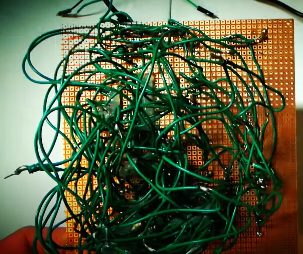
Yikes! Apple I Remake Protoboard Back
EEVlog & Raising Awesome Collaboration
You then found that chemical etching can save a bit of time snipping wires, stripping insulation, and trying to cut in bus wiring.


Crazy Inductor Learn-o-Nator Project
The bummer, though, is the chemicals require some decent PPE - hinting that they aren't too friendly for your health. Laser printing and ironing eats away your precious free time. Last, setup and cleanup time is a chore you'd rather just do without.
Of course, you could send it off to fab - but typically - you aren't ready for that long wait and expense, yet. You want to take your design for a test drive and look for improvements.
Well, there is a third option.
With the Arduino, makers began to make inexpensive CNC controllers. With inexpensive CNC controllers, makers brought even cheaper CNC mills. Open source then led to cloud utilities like Easel.com that optimized machine setups through the data of its users. At this point in maturity, PCB milling is the next logical choice for rapid prototyping.
With a staged approach, you call mill your traces and pads, drill your holes, and flip your board over for a second layer for about 30 cents a board.
MYTH BUSTING
I found some myths propagating on the internet concerning milling PCBs. However, I equally found some decent videos of it on YouTube. So, I had to see for myself.
Here are the top 5 myths for PCB printing debunked. Keep in mind - my use case is not for a pretty board with my name on it. I'm targeting a mid-design cycle rapid prototype that competes with a bread board for function and a manufactured board for form.
- Myth #1: The cost of the CNC doesn't justify its purchase.
Truth:
Versus other maker tools: its $170 bucks - costing you between a good solder station and a cheap 3D printer - and it can mill wood, plastic, and aluminum. Every seasoned maker should own or make one.
Versus an online Fabricator: In the US, eight 3"x3" designs pays for itself and you won't kick yourself for the mistakes you find after you submitted the order. For prototyping to your perfect final design, you'll shave off weeks of the design cycle. In the US, count on two weeks minimum round trip - waaaayy too long for rapid prototyping.
Versus Chemical Etching - with this, you still have to buy copper blanks, plus chemical, plus transparencies, plus wasted time doing considerable chores to prep and clean up.
- Myth #2: The accuracy of milling isn't sufficient for a PCB.
Truth: If you are doing through hole or SMD capacitors and resistors, there is absolutely no issue. If you can pull it off with transferring a laser printer for chemical etching, you can do it with the PCB. People that said this are surely using a ball end or flat end mill bit versus a single fluted V - or made no adjustments on their Design Rules specifications when laying out their board in the software.
- Myth #3: Setup time is greater than etching.
Truth: Setup is as simple as turning 4 screws. You don't even need to clean and polish the copper. Since the copper is pretty flat and the mill's base is pretty flat and you can hit the zero button wherever you want, you just slap it on the base and turn the screws. If you are going for perfection in trace widths, then yes you'll need to do a grid Z-probe to adjust your g-code zero to any board imperfections, but its still way faster than waiting on delivery of an ordered board.
- Myth #4: A milled board will not get the electrical property requirements resulting in issues with the board.
Truth: If you got it working on a bread board with a rat nest of 6 inch dupont cables, it will absolutely work with milled copper plate. You'll give it a better test by seeing how the ground plan affects any RF functionality you may be designing.
- Myth #5: You need a mechanical background to use a CNC.
Truth: Not at all. You just need to read, do, and find the next point of improvement. Humans aren't mechanically inclined anyway. It took rednecks until 2005 to apply the wheel to beer coolers.
COMPONENTS
After searching in the range of $150 to $3000, comparing the bang for the buck for my use case (fastest prototyping of a hobby PCB), I found a very versatile, but very broadly used machine for $170 US. It can mill wood, plastics, Copper, and aluminum (with patience).
The only other thing one needs are some copper blanks. A good, inexpensive option are the 70mm x 100mm dual sided blanks. You can see one in front of the CNC mill in the picture below:

CNC 3018 - Very Popular Entry Level CNC
SOFTWARE
There are several approaches for software. My favorite is always Autodesk Fusion 360. It will cover your whole project including schematics, board layout, making the g-code, as well as designing the enclosure and mechatronics around it. However, it's not exactly clickety boom to get you milling a quick demo. So, instead, I carved my first board using Easel.com.
Easel is a cloud based tool. The beauty of the cloud is it can get feedback from the users on the success of their design files. Over time, they have filled in all the settings that you'd normally do by hand in Autodesk Fusion 360.
Eagle, for designing the PCB, is now integrated in Autodesk Fusion 360. Alternately, one can use KiCAD or the stand alone Eagle to make their board. For this demo, I went to an old eagle file for an LED board I had fabricated for $8 which took 2 weeks to receive.
To add some tolerance for the traces and pads, just as I do for chemical etching, I beef up the traces to 12mil and the distances to 25mil.
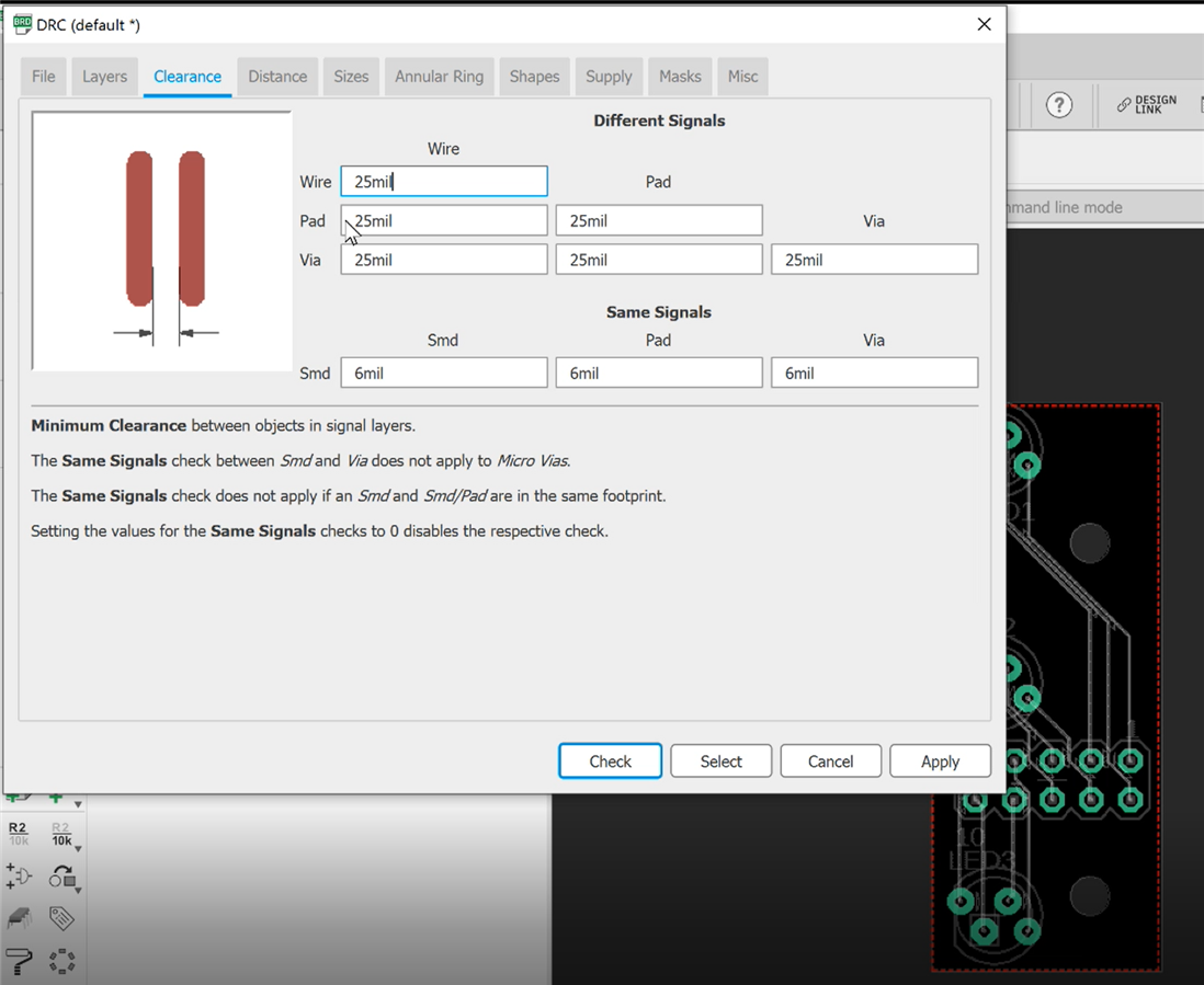
Setting the DRC to Give Back Some Milling Tolerance
After running the Autorouter and making any desired tweaks, I then print to PDF ensuring my scale factor is 1.
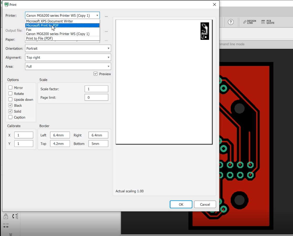
Printing the Circuit to be used as a Pocket Shape for the CNC
Easel, the CNC software, takes an SVG file. So, I went to an online PDF to SVG converter called convertio.co:
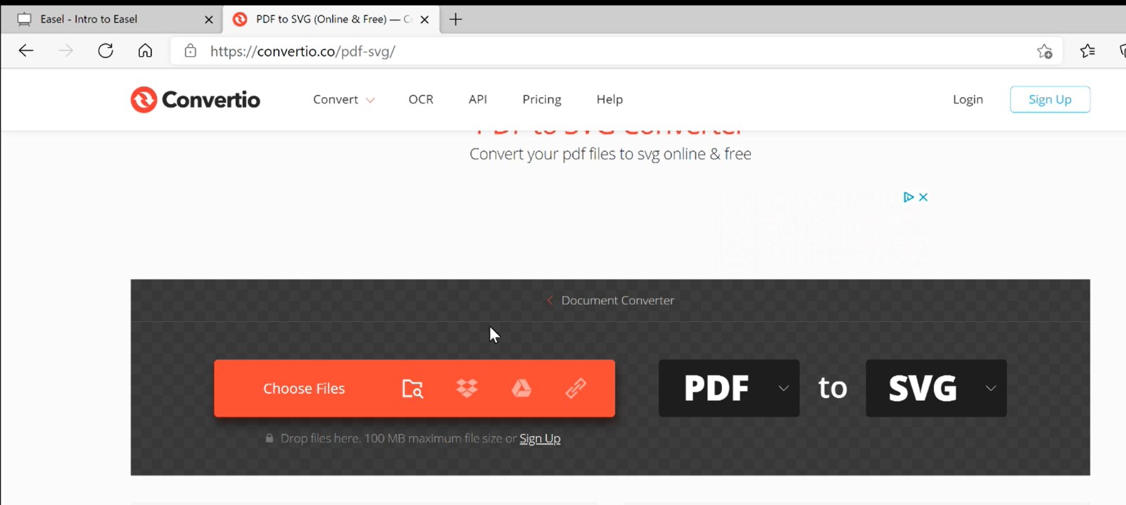
Convertio.co for PDF to SVG Conversion
Easel is as easy as 123: add your SVG file, add your material, and add your bit. There is a one time setup for your machine type so it knows what its talking to - but that takes about 1 minute and for the 3018 mill, it already knew it.

Adding the Dimensions for my Material - PCB is a standard material within Easel
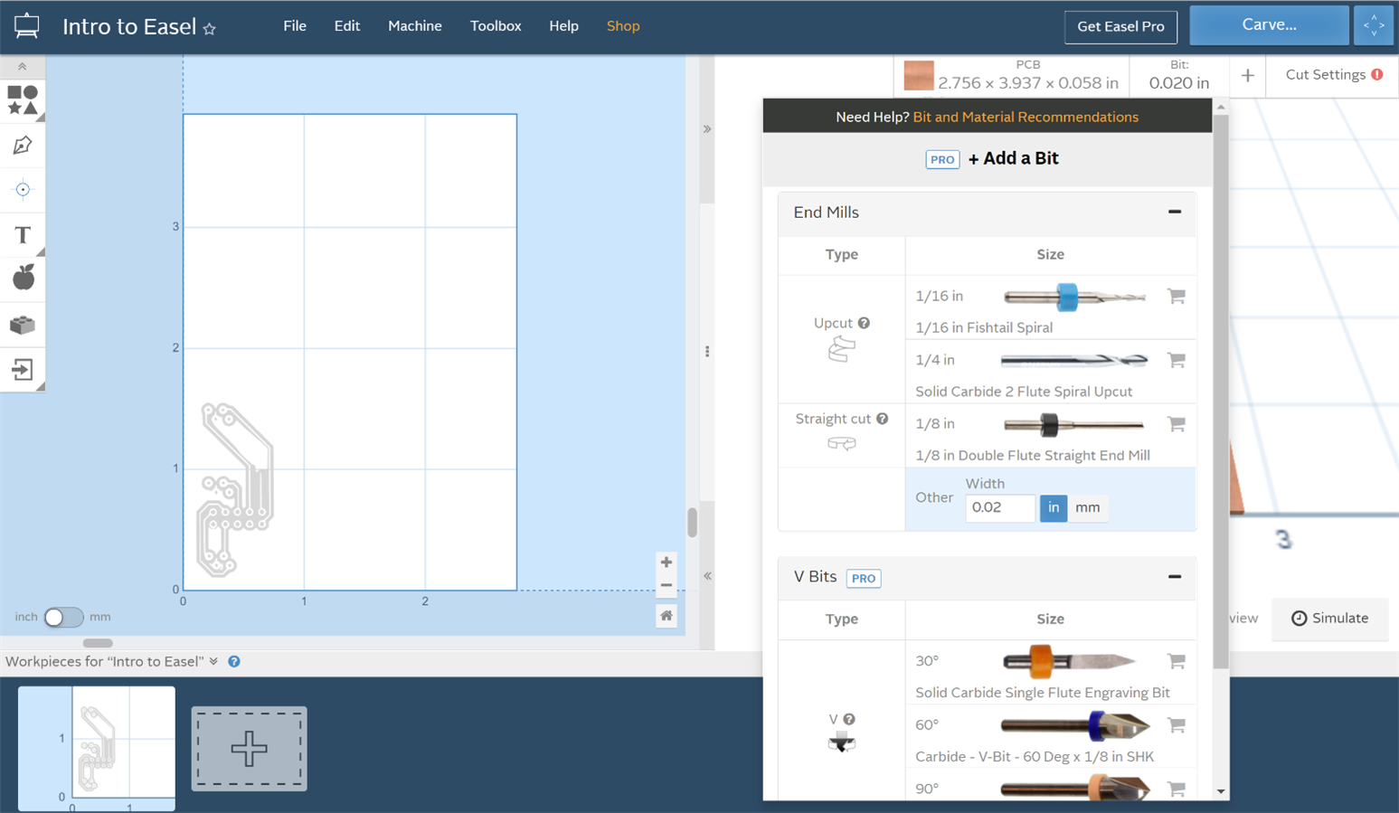
Selecting ones bit - I clicked "other" and set it to .02 in to keep it in the Free Version of Easel
When selecting the bit, I chose "other" set the diameter to 0.02". That's because I actually had a v type engraving bit, but would have had to upgrade to the pro version to use it. Close enough for horseshoes - again, I'm targeting mid-design cycle rapid prototyping here. Not wanting to compete with a fabricated board.
For the depth, I found I'm best to set it virtually to zero (0.0005"). You'll see why once I tell you my trick. At first I got all precise on setting my zero for Z. I found that it engraved a little deep. It made a functional board, but was just too goofy looking even for prototyping.
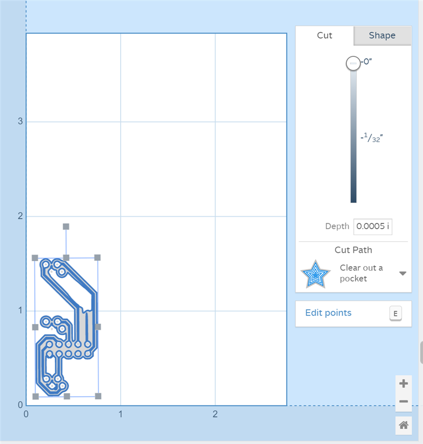
Setting the cut depth - basically setting the mill to darn near Zero
So, my final trick was when setting the Z, I actually ran the lead screw by hand until my actual V engraving bit poked the copper. The copper layer is super thin. Since the software always raises when not cutting, this ensured I'd get a cut regardless of the tolerance of the copper and machine.
CUTTING
This is definitely the fun part. You hit the CARVE button and away it goes freeing you up for other things in your workshop. However, it only takes a few minutes to carve out, so I just admired it working while I dust busted.
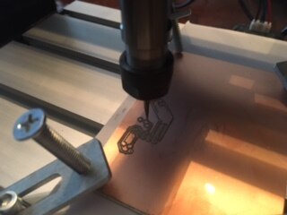
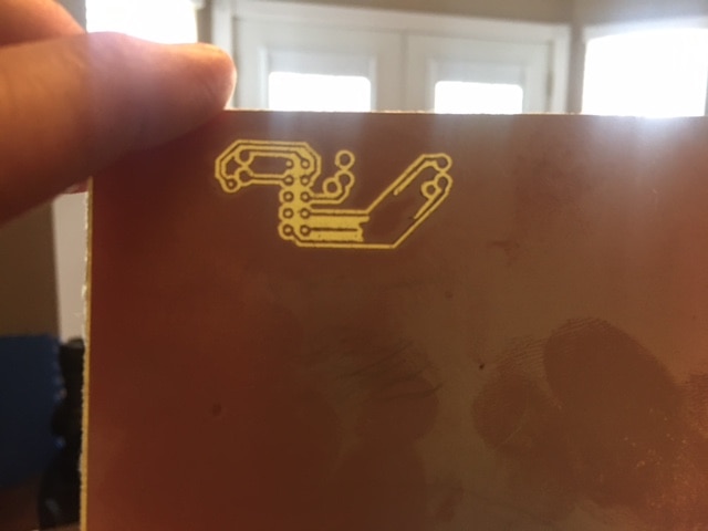
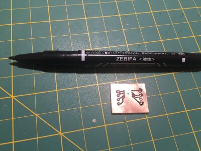
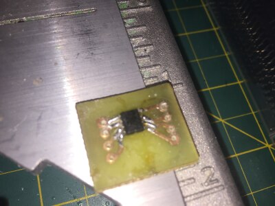
My First Carved Circuit using the CNC 3018
For drilling the holes, you can use easel to add a "Drill" or simply use circles as the same diameter of your bit, but to the depth of the board. Make sure you have something under the board so you don't damage your bit. Rather than plunging the V bit, you're better to simply swap bits and run the drilling as a separate process so you don't have a tapered hole you end up having to chase to get pins through.
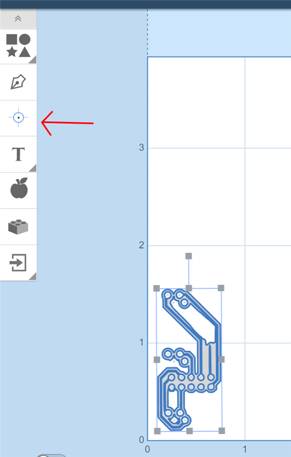
Pointing to the Drill Tool for Adding Holes
CONCLUSION
I found I waited way too late in life to get a hobby CNC. If you are into making anything, you should add it to your Christmas list. If you are into Maker Contests or making unique, one of a kind electronic gifts for friends and family, you should get one as well for your PCB rapid prototyping and minimize your project costs.
My wife very quickly realized I could carve out dollhouse furniture as well.

Milled Dollhouse Bar Table Along Side SLA Printed 3D Bar Stools
Have fun!
-Sean
Top Comments