


Background
I'm working on a long term project (several years now, if I'm honest!), to provide environmental monitoring and possibly some environmental control for my greenhouses. I've already investigated temperature monitoring using DS18B20 probes, which I've found very reliable and easy to use, provided you don't need a very long cable run!
I was inspired to pick the up project again by this blog: https://www.element14.com/community/community/project14/mixing-electronics-water/blog/2018/04/13/remote-temperature-monitoring by ntewinkel, which uses an ESP8266 device - great because it has on-board WiFi, can be programmed using the Arduino IDE and, very importantly, pretty economically priced - especially if bought from China or Hongkong!
As I reported in my own blog: https://www.element14.com/community/people/neilk/blog/2018/12/17/implementing-my-local-webserver-a-frustrating-yet-instructional-story , Nico was kind enough to give me access to his sketches and webserver programs and even to his private webserver for testing, until I got my own local webserver working. I've now developed Nico's ideas further to give me temperature monitoring from 2 x DS18B20 probes - one to be inside the green house and one to be outside, so I can see the temperature differential.
Initially I was using a Witty ESP8266 and am now currently using a Wemos D1 mini ESP8266. The temperature readings are logged on my webserver and can be displayed graphically on my PC or my android phone/tablet, ( if it is connected to my home WiFi - I have no plans to expose any of this on the wider Internet - ie I have no aspirations to check the temperature of my greenhouses whilst I am on holiday!).
Unfortunately, in the late autumn I had to rearrange the 250V AC mains power supply to the pond. As a result, one greenhouse was (temporarily) disconnected from the mains supply. The other greenhouse does not yet have a mains power supply. All the required armoured cables are in place, but at the moment the weather is not conducive to sitting hunched up on a stool for several hours, terminating armoured cables. Hence the interest in battery power!
There is a lot of information available about the current consumption of the ESP8266 in normal mode, when using WiFi, when in deep sleep etc. I have taken note of this and am now embarking on what I consider to be the investigation of a "real world" example.
The Current Temperature Monitoring Sketch
The current sketch uses Simon Monk's Timer Library: http://www.doctormonk.com/2012/01/arduino-timer-library.html to provide a 1 minute interval timer to control the reading of the probe temperatures and also to flash the on-board LED on the ESP8266 at 1 second intervals - a "heartbeat" to show that the ESP8266 is actually doing something . The temperature readings are posted to the webserver, date/time stamped, using a .php script based on Nico's original. During the probe read and data posting, the on-board LED is permanently illuminated
I decided to investigate the effect which of the different elements of the current sketch have on power consumption BEFORE doing the obvious things of putting the Wemos to sleep between readings.and increasing the time interval between readings.
The Battery Setup - Attempt 1
As a household, we were in need of a battery phone charger/power bank, so I invested in a 1000mAh model made by a Chinese (surprise!) company called DIVI.
Unfortunately, what I didn't expect was that the DIVI unit would be too clever! It is designed to shut down 30 secs after a connection is made to its USB socket, if the connected device does not draw more than an (unspecified, in the very limited documentation!) minimum level of current.
Guess what? My little Wemos set-up, with its flashing LED and twin DS18B20 probes, DOES NOT draw enough current to keep the DIVI unit active. So I plug in the Wemos, the heartbeat LED starts flashing and then 30 seconds later it stops!
We did need the power bank anyway!
The Battery Setup - Attempt 2
The starting point for my second attempt is a Wemos D1 Battery shield, to which I soldered 8 pin female headers with long pins so it would plug directly into the Wemos D1 mini (the photograph shows the Battery shield without the headers)

I also purchased an 18650 2400mAh 3.7V Li-ion battery and battery holder which comes with bare ended wires:

The Battery shield has 2 connectors - a micro USB, for charging and a XH2-2.54mm shrouded male to connect the LI-ion battery. I didn't have a mating connector for the battery so I made up a little strip-board circuit, consisting of a (reclaimed) 2-way screw terminal block and a 3-way female header (the outer pins of the header line up with the 2 ways of the screw terminal block. The 2 wires from the battery holder are connected into the 2-way screw terminal block. To avoid the risk of a short circuit, I put 2 layers of insulating tape on the copper side of the strip-board. I also made up a short cable to connect the female header to the XH2-2.54mm connector on the Battery shield:

Before I made the decision to try the Wemos D1 battery shield, I'd looked at a number of videos and articles on the web. This excellent account of the battery shield is worth mentioning: https://arduinodiy.wordpress.com/2016/12/25/monitoring-lipo-battery-voltage-with-wemos-d1-minibattery-shield-and-thingspeak/
I learned a number of important things from this article, including how easy it is to monitor the battery voltage. The ESP8266 A/D converter is fed from the Wemos pin A0, via a voltage divider consisting of a 220k resistor between the Wemos Pin A0 and the A/D pin of the ESP8266, and a 100k resistor from the A/D pin to GND.
The A/D converter has a maximum input voltage of 1.0V, giving a value of 1023, when read in a sketch. The presence of the voltage divider therefore allows a maximum voltage of 3.2V to be applied to to pin A0:
1.0V = 3.2V x 100 / ( 100 + 220 )
The above article then shows how connecting a 100k resistor between A0 and the + side of the battery connector will allow a maximum of 4.2 volts to be monitored:
1.0V = 4.2V x 100 / ( 100 + 100 + 220) This is ideal because the expected fully charged state of the 18650 battery is 4.2V.
Having inserted the resistor, I then needed to modify my ESP8266 sketch to post the battery voltage at regular intervals.The easiest way to do that was to add a second POST command which used a different .php script to post the battery voltage to another file, immediately after posting the temperature probe readings.
The Wemos D1 battery shield includes 2 LEDs next to the Tx pin - a red one which is illuminated whilst the battery is charging and a blue one which is illuminated when the battery is fully charged. After charging the battery for about 1 hour. my DMM showed the battery voltage to be around 3.8V
I was impatient to see my creation working, so I disconnected all the leads and cables from the battery shield and carefully plugged the shield into the Wemos D1 mini. I then connected the DS18B20 temperature probes to the assembly, connected the battery and hey presto we were away.
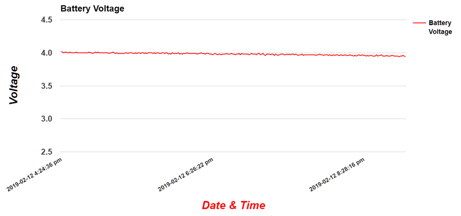
Here is the battery voltage chart, with the voltage readings taken at 1 minute intervals. I think the "blip" at the end of the chart was caused by me touching the assembly, in order to disconnect the battery just as a reading was being taken:

Here are the temperature readings for the same period, again at 1 minute intervals - Sensor 001 is hanging over my desk and Sensor 002 is on the windowsill, next to a double-glazed window.
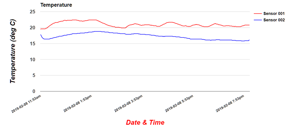
The above charts are based on Nico's original code and are totally reliant on the APIs provided by Google: https://developers.google.com/chart/interactive/docs/quick_start
A Fully Charged Battery
I decided to charge the battery fully and repeat the experiment with the original ESP8266 sketch. I dismantled the whole assembly, unplugging the battery shield from the Wemos D1 mini. I then plugged a phone charger into the battery shield. The voltage from the battery connector (without the battery connected) reads about 4.3V on my DMM. I connected the battery up and left it to charge, checking periodically. The voltage measured across the battery seemed to stick at about 4.08 to 4.10V, even after about 5 hours. The blue LED on the battery shield, which indicates full charge, never came on.
The fully charged voltage of the 18650 LI-ion battery is supposed to be around 4.2V. My DMM is quite inexpensive and probably a biy lacking in accuracy, but the fact that the fully charged LED never came on suggests that perhaps my DMM isn't the issue here! I reconnected everything and ran the system again for a few hours. I got an almost identical discharge pattern. I repeated the charging process and once again, after 2.5 hours the battery reached 4.08V. After a further 2 hours, it was only 4.09. I suspect that this is fully charged for my battery!
I was slightly concerned by the open circuit voltage of the battery charger - 4.3V. It's possible to imagine a situation in which that voltage could be applied to A0, thus delivering more than 1.0V to the A/D input of the ESP8266 chip. I don't know whether such an overvoltage would damage the ESP8266. However, the clever people at Wemos have recognised this and in a later version of the shield(1.3), which I don't have, they have included a 130k resistor which can be connect between the battery positive and A0, with a jumper (actually 2 solder pads).
Taken from the v1.3 schematic:

This allows for a maximum of 4.5V to be applied to pin A0, without exceeding the 1.0V limit on the A/D pin. Unfortunately, I didn't have a 130k resistor, so I used a 120k instead, thus allowing me a maximum of 4.4V. I hope that will be sufficient margin.
Impact on Power Consumption - 1 LED
The simplest modification which might reduce power consumption would be to reduce the amount of time the LED is illuminated. I originally included the "heartbeat", which flashes the LED on for 1 second and then off for 1 second all the time, so you can see that something is happening. I decided to let the heartbeat run for the first minute - ie until the first time the temperature probes and the battery voltage are read and uploaded to the server. This was a simple modification.
With an almost fully charged battery I ran the system for about 8 hours. I was disappointed to find that, at least with the naked eye, there seemed to be little change in the discharge rate. I won't bother to show the resultant graph here! Since I'm looking for a substantial reduction in power consumption, there's little point in analysing the discharge graphs in detail and it's pretty clear that tinkering with the LED any further, is irrelevant at this stage!
It looks as if I have to take the big step and implement Deep Sleep. Actually, this isn't as difficult as it may sound - after I've stripped out all the code that uses Simon Monks Timer Library.
Impact on Power Consumption - 2 Deep Sleep
The Deep Sleep requires a simple hardware modification - a jumper is needed between the Reset Pin and and Pin D0 of the Wemos D1 mini. Pin D0 on the Wemos maps to GPIO_16 on the ESP8266 - this has a WAKE feature. During the Deep Sleep period, D0/GPIO_16 are held high. At the end of the Deep Sleep period, D0/GPIO_16 goes low, pulling down the Rest Pin and thus restarting the ESP8266. The program then executes and, when complete, the ESP8266 is put back into Deep Sleep.
Deep Sleep is implemented with a simple command at the end of the sketch::
const int deepSleepSecs = 60;


unsigned long int actSleepTime = deepSleepSecs * 1000000; //microseconds


ESP.deepSleep(actSleepTime);// Deep Sleep
The Deep Sleep period becomes the time interval between readings and the first set of readings are taken shortly after the ESP8266 starts. In the original, timer based version, the first reading wasn't taken until the end of the first time interval.
I made the modifications and tested the new sketch still connected to my PC, so I could read all the diagnostics via the IDE Serial Monitor. When I checked the log files on the server, everything was working, so I disconnected the USB and reconnected the battery shield and battery and off we went.
Here is a graph of the first 4 hours with a 1 minute Deep Sleep interval::

The last reading is at 4:10 pm. As can be seen, the battery voltage has barely dropped over a 4 hour period. During that 4 hour period, temperature and battery voltage readings were taken at 1 minute intervals.
An unintended consequence of introducing Deep Sleep is to make the actual time interval between readings 1 minute and about 10 seconds: the sketch takes about 10 seconds to execute - about 5 seconds for each server update. To counteract this, I introduced a correction factor to subtract 10 seconds from the basic Deep Sleep time and added seconds to the date/time stamp display so that I could see the time issue more clearly.
The horizontal axis of the chart is set to display the date/time stamp every 120 readings - ie every 2 hours with a 1 minute interval. As the chart shows, there is still a drift of more than 1 minute every 120 readings. More of this later!
I left the Wemos running on battery overnight and here is the resultant chart:

We can easily estimate the battery voltage drop to be about 0.25V over about 18 hours or so. Not really good enough for a serious, remote monitoring device!
When I looked in detail at the 2 log files, I could see that there was a roughly 5 second difference between the date/time stamp for the temperature probes and that for the battery voltage. There is a lot of information available about ESP8266 power consumption under different conditions and one particular thing caught my attention: how the WiFi consumes a great deal of power. I decided to investigate whether sending the temperature readings and the battery voltage in a single POST command would have a significant impact on power consumption.
Impact on Power Consumption - 3 Deep Sleep with Minimum WiFi
I modified the sketch to send all the data in a single POST command and reduced the sleep time correction factor from 10 seconds to 5 seconds. I also wrote a new php script to respond to the new POST command and write the temperatures and battery voltage to two different files on the server.
After correcting a few typos, I got the modified software working and here is the result:

The last reading taken before I switched off was at 1:27:54 pm.
This is a massive reduction in power consumption, the chart showing a drop of about 0.1V over a period of just under 20 hours. The datasheet for the battery shield quotes a Lithium battery voltage range of 3.3 to 4.2V. However, in this article:
https://arduinodiy.wordpress.com/2017/01/02/reviewing-the-wemos-battery-shield/ the author notes that his Wemos stopped working when the battery voltage had reached 3.56V
If we assume that the battery discharge will be linear down to 3.6V, , then it will take approximately 100 hours or just over 4 days, to discharge the battery from 4.1V to 3,6V. This is becoming a realistic option, when we take into account that readings at 5 minute, or possibly even 10 minute intervals, will be acceptable for monitoring the temperature of a greenhouse! This puts battery life at, hopefully, up to at least 20 or even 40 days.
Note that the timing is still slightly off, but that it drifts up and down. Over almost 20 hours, the error is negligible.
Further Thoughts
- Diagnostic messages sent to the IDE serial monitor, are still being output, even though there is no where for them to go. Would commenting them out reduce the execution time of the sketch and therefore further reduce power consumption? Maybe worth a try
- The Wemos D1 mini is said to consume around 77 microAmps in Deep Sleep. The on-board USB-Serial interface is said to consume about 50 microAmps, making a total of 127 microAmps for the whole system.
- Presumably an ESP8266 presentation like the Witty, which has its USB-Serial interface on a removable board, would consume less power when used without its USB-Serial interface. Depending on the balance between the power consumed when awake and the power consumed when asleep (depends on sleep duration), this could significantly increase battery life - room here for another investigation!
I now intend to try out the prototype out in one of the green houses.
Top Comments