


My Peruvian mate martinvalencia and I purchased a set of 25LC256 SPI serial EEPROM chips. Our plan was to get them working with the Texas Instruments Hercules LaunchPad MK II. That was back in January. And then we stalled. Martin has restarted the exercise and I'm going to play along.
This blog is our path from Zero to Hero. Feel free to jump all over us while we're doing things the wrong way. |
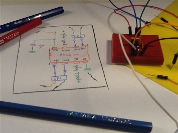
Wiring the LaunchPad to the EEPROM
No rocket science here.Although the signals are differently named by each Microchip and Texas Instruments, they are the same thing.
To overcome that, I've invented my own convention, so that neither of them gets away with it  .
.
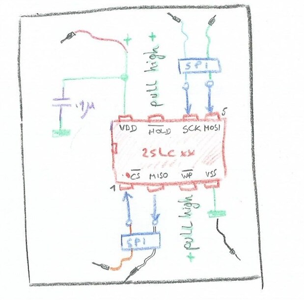
~HOLD and ~WP
I've checked what to do with the pins. I don't need them. To take care that the chip is not write protected and not in hold mode, I pull them high permanently. It seems I can do that directly to the positive rail without resistor. I may check later with my µCurrent to see if they pull any real current.
You can find the use of these two signals in the datasheet. |
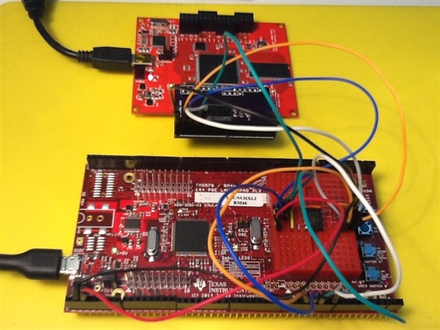
On the Hercules Launchpad, I've selected the SPI module 3.
I didn't do that with a particular functional reason. It is the one that's broken out to both the BoosterPack headers and the breakout pads on the side.
I figured that this could be useful later on.
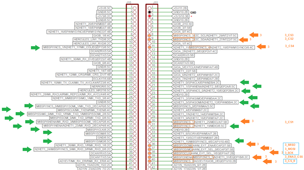
The pins that have a blue rectangle around them in the picture above are the ones I'm using.
The chip select goes to J11.40, clock to J11.38, master out to J11.37 and master in to J11.36.
I've placed a .1µ capacitor over the power rails, close to the ic.
Consistent Color Coding
I've kept the colors of the four SPI signals consistent in my drawings and with the patch wires.
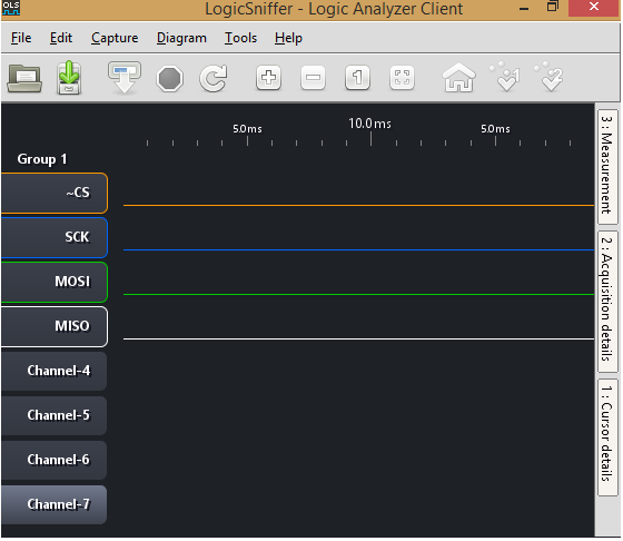
I'm keeping this consistent in my logic analyzer. I'm setting it up to show the signals with those same colors and names.
My conventions:
| signal (Microchip) | signal (Texas Instruments) | signal (my blog here) | color code | description |
|---|---|---|---|---|
| ~CS | NSC | ~CS | orange | chip select |
| SCK | CLK | SCK | blue | serial clock |
| SI | SIMO | MOSI | green | data master -> slave |
| SO | SOMI | MISO | white | data slave -> master |
Configuring the Logic Analyzer
My Papilio FPGA board has logic analyzer duty.
As client, I'm using JaWi's Logic Sniffer client. I'm configuring it so that its colors match my drawings abd wires, and I've also labeled the signals to my naming convention.
Setting the colors and labels
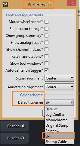
The program doesn't save your color settings when you save a project. The easiest way to set the signal colors is by creating a color schema.
Just take one of the existing files in <ols_install_folder>/plugins, edit it as shown below, and save it under a new name.
<ols_install_folder>/plugins/ols.ui.colorscheme-spi
# The name of this color scheme
ols.color.scheme.name = SPI


# The default background color
ols.background.color = 1e2126


# The default color used for text shadows
ols.shadow.color = 151620


# The default color for channel group 1
ols.channelgroup1.default.color = 92d4ca
ols.channelgroup1.channel1.default.color = FF9900
ols.channelgroup1.channel2.default.color = 0066FF
ols.channelgroup1.channel3.default.color = 00CC00
ols.channelgroup1.channel4.default.color = FFFFFF
ols.channelgroup1.channel5.default.color = 1e2126
ols.channelgroup1.channel6.default.color = 1e2126
ols.channelgroup1.channel7.default.color = 1e2126
ols.channelgroup1.channel8.default.color = 1e2126
# ...
You can then select this color schema as your default:
You can rename the signals by double-clicking on them and typing the new name. These settings are stored when you save your project.
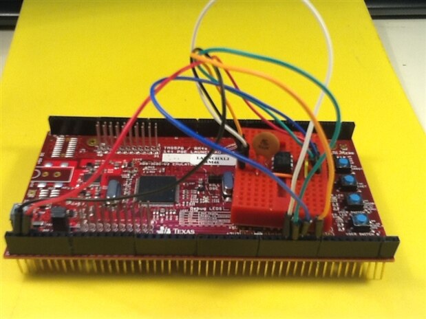
Connecting the Papilio.
I'm connecting 5 wires: GND and the 4 SPI signals. You can read how use your Papilio as logic analyzer here: Make a Logic Analyzer from your Dev Kit Part 2: Papilio FPGA.
Because there is no level translation needed in my setup here, I could use the Papilio without input buffer.
I'm leaving it in anyway to make it easy to disconnect the LA from the circuit in one go when needed. It just acts as a connector in this design.
| Related posts |
|---|
| part 1: from Zero to Hero |
| part 2: this post |
| part 3: Testing SPI Protocol with Bus Pirate |
| part 4: First Trial on the RM46 |
Top Comments
-

Jan Cumps
-
Cancel
-
Vote Up
+1
Vote Down
-
-
Sign in to reply
-
More
-
Cancel
-

martinvalencia
in reply to Jan Cumps
-
Cancel
-
Vote Up
+1
Vote Down
-
-
Sign in to reply
-
More
-
Cancel
-

Jan Cumps
in reply to martinvalencia
-
Cancel
-
Vote Up
+1
Vote Down
-
-
Sign in to reply
-
More
-
Cancel
Comment-

Jan Cumps
in reply to martinvalencia
-
Cancel
-
Vote Up
+1
Vote Down
-
-
Sign in to reply
-
More
-
Cancel
Children