


I've been spending some time thinking about best using an ADC and I've done some weighing up of suitable components. I've half settled on a Microchip MCP3248 rather than a TI ADS1115. The Microchip has slightly better specs than the TI but it is limited in range on its inputs: -2.048V to +2.047V differential, 0V to +2.047V single ended; the TI has a more flexible option of ranges which expands its single-ended ranges, including a -4.096V to +4.096V, 0V to +4.096V single ended.
Anyway that's not really the purpose of this post per se except in so much that I may change my mind on the Microchip. Currently, I would be limited to a 0V to 2.047V signal range which is half its available Full Scale Resolution (FSR); this is half that of the TI of course. The range is fine if, for example, I had to sample a voltage drop over a current sense resistor but not so much if I had to measure a voltage of, say, 0V to 5V. I'm describing here an option I'm considering to improve the resolution of the ADC and I thought it might make an interesting read. I want to change an incoming 0V to 5V signal to a -2.048V to +2.048 signal to make full use of the ADCs FSR.
The datasheet has this to say:
The differential voltage at the input pins (without PGA) is: Vin = CH+ - Ch-. The differential input voltage range is -Vref <= Vin * PGA <= Vref - 1LSB; essentially the input range is -2.048V to +2.048V after applying any gain.
What this means is that I cannot apply a 0V-4.095V on the CH+ pin with a -2.048V on the CH-. So if I scaled 5V to 4.095 on CH+ with -2.048V on CH- then Vin, according to the formula is 4.095 - (-2.048) = 6.143V. I have to scale 0V to 5V to a range -2.048V to 2.047V and apply a -2.048V on the CH- pin.
In software, I could lift the output code up by 2.048V output code so -2.048 becomes 0V.
I'm working from this document which explains the maths and design very well. I'm summarising a lot here, and missing out a fair bit of the algebraic manipulation so it's worth reading the document for a full understanding. This is new to me, so here goes.
Scaling and biasing just means creating a new signal from an incoming signal as a linear transformation. This can be represented by formula Vout = s * Vin + b, where s is the scale and b is the bias; the formula will look familiar to anyone who has graphed a straight line and it's essentially the same formula as the transfer function in a DAC and ADC - scale and bias are just synonyms for slope and offset. Given two points on a straight line, we can calculate:
Scale = deltaVout / deltaVin
Bias = Vout - scale * Vin
With those two equations we can specify an input and output range and determine the scale and bias.
Easy Example
Map a 0V to 5V signal to a 0V to 2.048V signal.
- deltaVout is 2.048 and deltaVin is 5
- scale, s = 2.048 / 5 = 0.4096
- When Vout is 0 then Vin is 0 so Bias, b = Vout - s * Vin = 0 - 0.4096 * 0 = 0
- The final transformation for this is, Vout = 0.4096 * Vin + 0
Specific Calculation
Map a 0V to 5V signal to -2.048 to 2.047 signal
- deltaVout = 4.095, deltaVin = 5
- s = 4.095 / 5 = 0.819
- When Vout = 0 then Vin is 2.5 so b = 0 - 0.819 * 2.5 = -2.0475
- The final transformation for my need, then, is Vout = 0.819 * Vin + (-2.0475)
That's easy enough but this transformation has to be implemented through a voltage divider and a bias voltage source:
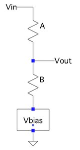
Vout can be calculated as, Vout = [B/(A+B)] * Vin + [A/(A+B)] * Vbias
Which looks just like the original linear transformation, Vout = s * Vin + b so
s = [B/(A+B)]
b = [A/(A+B)] * Vbias
This work quite well in general terms. Make A = B and choose 5V for Vbias and -5V to 5V maps into 0V to 5V. Not what I need but shows the principle.
From all this, and doing the necessary algebraic finagling between these formulas we can calculate:
ratio of divider, r = deltaVout / (deltaVin - deltaVout) = 4.095 / (5 - 4.095) = 4.525
Vbias = Vout - r * (Vin - Vout) = 0 - 4.525 * (2.5 - 0) = -11.3125V [where Vout = 0 when Vin = 2.5]
LTSpice confirms this:
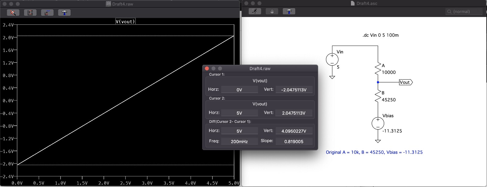
But -11.3125V isn't a very convenient value! Turns out that I can make the Vbias part of the design and choose that value up front.
There's a lot of algebraic finagling and maths in this next step - add a third resistor. I can't begin to explain it simply - it involves linearity and superposition of partial results - and just in case anyone thinks I'm a bit of a maths genius, let me burst that bubble and point you, again, at this document. It explains better than I can what is going on here.
Nonetheless, I shall put some brief notes here. In order to specify the Vbias voltage, we use three resistors as follows:
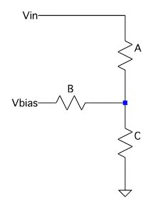
The basic formula from this is (gird your loins):
Vout = [ ((B * C) / (B + C)) / (A + ((B * C) / (B + C))) ] * Vin + [ ((A * C) / (A + C)) / (B + ((A * C) / (A + C))) ] * Vbias
It looks complicated but you can still see the scale and bias linear transformation in it. From this we want to supply scale, bias and Vbias in order to calculate the values of resistors A, B and C. There then follows a fair bit of algebra work (explained in the linked document) to end up with new looking (but the same) formulas for scale and bias:
s = ( 1 / [ A * (1/A + 1/B + 1/C) ] )
b = ( 1 / [ B * (1/A + 1/B + 1/C ] ) * Vbias
which is just a re-arrangement of the above complex formula in different algebraic terms. Multiplying top and bottom of both by C:
s = ( (C/A) / (C/A + C/B + 1) )
b = ( (C/B ) / (C/A + C/B + 1) ) * Vbias
Here it gets tricky. We can work those formula through with a scaling factor alpha=(1/A + 1/B + 1/C) and end up with
s = 1 / Aalpha
b = Vbias / Balpha
and combining with the original formula for calculating s and b:
Aalpha = deltaVin / DeltaVout
Balpha = Vbias / (Vout - Vin / Aalpha)
Calpha = (Aalpha * Balpha) / (Aalpha * Balpha - Aalpha - Balpha)
So, now we can work out the values for three resistor solution:
Vin = 0V to 5V, Vout = -2.048V to 2.047V, Vbias = -2.048V
Aalpha = 5 / 4.095 = 1.221
Balpha = -2.048 / (2.047 - 5 / 1.221) = 1 [when Vin is 5V, Vout is 2.047]
Calpha = (1.221 * 1) / (1.221 * 1 - 1.221 - 1) = -1.221 <------ Uh-oh!
A = (10K/1.221) * 1.221 = 10K
B = (10K/1.221) * 1 = 8.19K
C = (10K/1.221) * -1.221 = -10K <------ !!
Clearly an unworkable solution except in LTSpice:
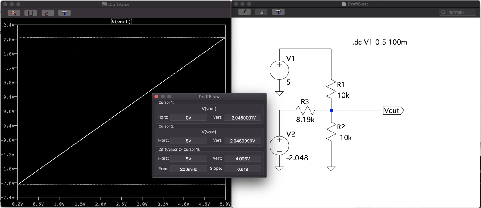
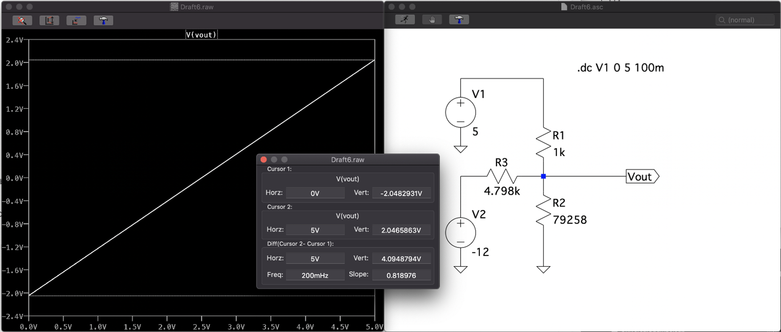
So there is only one option - change the output range and/or Vbias. Keeping Vbias at -2.048 won't give any workable solutions and, in fact, the only workable solution I found was by changing Vbias from -2.048:
A -12Vbias would give me a full output range of -2.048V to 2.047V:
A -5Vbias would give me a range of 3.5V:
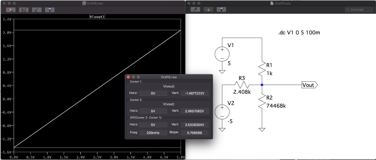
Note, changing the resistor values to obtainable values has a small impact on the range.
Either of these solutions still leaves me needing to create a -2.048V for the -ve differential input to the ADC. If I did this, I would need the following power rails for the solution: +5V for the ICs, -5V for the buffering OpAmp, -12V for the bias voltage and -2.048V for the differential input. Here's what it would look like in practice (including a not-calculated low pass filter before the ADC inputs):

Even in LTSpice without modelling any parasitics it's showing that it isn't perfect. Of course, even without this, accuracy would still be impacted by parasitic and other circuit elements. I wouldn't use an OPA192 to buffer the -2.048V in practice as it's too expensive so I'd just use a jelly bean part.
It's got me wondering if it's worth the effort and whether or not I should just stick to using the single ended range or switching to the ADS1115 with its larger single ended range. For a different voltage range, e.g. 0 to 30V, a different set of values will be needed.
Anyway, the main reason for posting this is I thought the whole process was interesting enough to share.
Top Comments