


This is another exploratory blog relating to bipolar junction transistors (BJTs). It follows on from a previous blog which
can be found here Transistors: Saturation
Be aware that I'm not an expert in all this: I'm studying it and you're looking over my shoulder as I experiment and explore
the subject. So this is not a tutorial and it's possible that some of my explanations may, at times, be wrong.
Introduction
In the previous blog I looked at the collector and base saturation voltages of small bipolar junction transistors at moderately
high collector currents in the range up to 200mA. I took my cue for that from the kind of figures seen in datasheets. It gives
a sensible idea of the kind of collector saturation voltage that might be encountered when using the transistor to switch a
load of some sort.
Something that was evident from doing that experiment was that there was a fair amount of variation in saturation voltage
over the range of currents I looked at.
I became curious to see in more detail what happens at lower currents; whether the saturation voltage would keep going down
or level out. I also wanted to try out a technique (inverse mode operation) that is sometimes suggested in old books on transistor
design for reducing saturation voltage in circumstances where it might be quite critical; I was curious to see if it would work with
modern transistors.
The current source I used in part 1, with a differential amplifier to amplify the voltage from a current-sense resistor and a second
op amp to compare that to an input voltage and run a control loop with the help of an output transistor, wasn't particularly stable
and had particular difficulty with the 2N3904 part. For this blog I decided that as the currents involved could be delivered directly
by an op-amp output I'd try something like a pair of Howland current regulators, one for the collector and one for the base.
Saturation voltage at lower currents
To start with, I'm going to stick with the ten-to-one ratio between collector current and base current and have the collector current
in the range 0-10mA and the base current as 0-1mA. Here is the circuit

and here it is built on a breadboard (the transistor under test in that shot is the 2N30532N3053 which is housed in a TO39 can)

Note that the circuit inverts, so I had to arrange for the ramp from the generator to go from 0V to -1V to sweep from 0mA to 10mA
for the collector and 0mA to 1mA for the base.
To test that the currents were correct, I placed 100R resistors to ground instead of connecting to the transistor and quickly checked
that the traces were linear ramps and had the correct voltages to correspond to the currents, which they did. It isn't amazingly precise,
but it's good enough for this blog and to get a feel for how the transistors behave [I can see myself automating this at some point with
processor-controlled voltage and current sources].
I'm going to test again the three transistor types I tried previously.

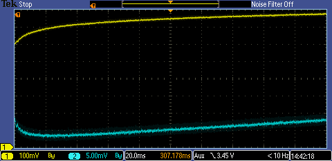
Here are the traces (the yellow trace is the base voltage, the blue trace is the collector voltage):
2N3904:

BC548:

2N30532N3053:

There's quite a variation between the devices. All in all, the 2N3904 looks quite poor compared to the others. The BC548 has a higher
gain than the other two, so that would perhaps suggest that the rise again in the saturation voltage at low currents with the other two
may come from the device starting to come out of saturation as the gain falls off.
The current sources now work a lot better, though the somewhat imprecise tracking between the two is messing things up a little on
the lefthand side where the base current is only a few tens of uA.
Inverse mode operation
This sounds very technical but simply means using the transistor upside down, so that we're swapping the emitter and collector over.
The transistor is very inefficient operated like this and will have hardly any gain, but it might have a lower saturation voltage. Old books
used to suggest this a way of getting a very low saturation voltage for switches used in chopper amplifiers but I suspect that with
efficient modern transistors the benefits might not be so great.
To make this work, I'm going to have the base current the same as the collector current so that I'm not asking for any current gain at all
from the transistor; that gives it a good chance to bottom and get to the saturation point. For a fair comparison, I'll test the transistor
both ways round because the saturation voltage one-to-one will probably be different to what I measured before.
Here are the curves. For each transistor type, the first screen capture is for the normal mode and the second one is inverse mode.
2N3904:


BC548:


2N30532N3053:

Conclusion from that I think is that there is value in driving the base harder in the normal mode but that the benefit of inverse mode is
only a slight improvement (possibly a mere 10% or 20% reduction in the saturation voltage). [On a practical note, something to watch
out for if you were tempted to use a transistor in inverse mode is the breakdown voltages - the reverse breakdown voltage of the
base-emitter junction is normally something like 8V or 9V (it usually gets specified as either 5V or 6V on a datasheet). In inverse mode that
then determines how far above the base you can have the emitter that is now pretending to be the collector.]
So, beware of what you read in 50-year-old books. Caveat scholaris! (or whatever the Latin would be).
What I have shown, though, is that if the saturation voltage is important to you then choice of device makes a considerable difference,
as does how hard you drive the base (but keep in mind it will slow further the turn-off time and add to the dissipation) and also the
collector current you work at (if you happen to have a choice in that).
Bear in mind that these aren't precision measurements and if you wanted to apply this in some way you'd need to do some experimenting
of your own. In particular, I've avoided any mention of how the voltage varies with temperature (it does) and that then means that device
dissipation will be an issue, particularly at the higher currents [when manufacturers do these tests, they do them with a pulse test where
the device is on for just 2% of the time to avoid the temperature effects].
If you found this interesting and would like to see more of the blogs I've written, a list can be found here: jc2048 Blog Index
Top Comments