


Part 2 – RoadTest Rohde & Schwarz NGL201 Power Supply
This is the second blog post in a series that will cover my work for road testing the NGL201 power supply. I am planning to have three parts: part 1 has been posted at this link (+) Part 1 – RoadTest Rohde & Schwarz NGL201 Power Supply - Cosmin Iorga's Blog - Personal Blogs - element14 Community, part 2 is this post, and there will be third part that I will post as soon as I get the corresponding work done and documented. This part will cover various performance parametric and functional measurements.
1. Output Voltage Ripple and Noise
This set of experiments evaluate the NGL201 output noise and ripple. The test setup for measuring the voltage ripple consisted of a 2 Ohms resistor connected as load to the NGL201 power supply in a 4-wire configuration. The setup is shown in the following figure:

The NGL201 has been programmed to 1V, 2V, 3V, 4V, 5V, and 6V. The peak-to-peak and rms ripple has been measured at the load with an R&S RTB2004 oscilloscope. The first set of measurements show very high ripple and noise, so I have further investigated the root cause especially if the measurement setup couples noise from the surroundings. The first set of measurements is shown in the figures below. The ripple + noise has been measured using the measure function of the R&S RTB2004 oscilloscope, and it is shown on the screen encircled in the picture with purple colored line.


The expectation was to see voltage noise + ripple below 2mV pk-pk. Since the noise levels are much higher than the expected I have looked into any possible noise coupling into the measurement setup. First experiment was to short the probing clips and measure the noise of the cable only (plus the input noise of the oscilloscope). Then I have adjusted the previously measured values by subtracting the test fixture noise as rms (as shown in the table):

The adjustment subtracted the rms noise of the probing cable from the previously measured values (subtracted as rms values, so square root of squares). The resulted noise (noise + ripple) was still very high, so I decided to remove the resistor thermal noise (by disconnecting the resistor load) and to remove the noise coupling on the wires that connect the NGL201 power supply to the load. These changes are reflected the setup shown in the figure below:

The oscilloscope is connected with a coaxial cable directly to the power supply output terminals (with a short wire adapter that I have built myself, and which may introduce some coupled noise but much less than the wires used before). The waveform shows some “occasional” spikes superimposed on a “more stable” noisy waveform of about 4.73mV pk-pk. More work to clean up the test fixture got rid of the occasional spikes and left the 4.73mV noise there. Next, by zooming into the time scale I have noticed that the 4.73mV pk-pk noise has an oscillatory behavior, as shown in the figure below:
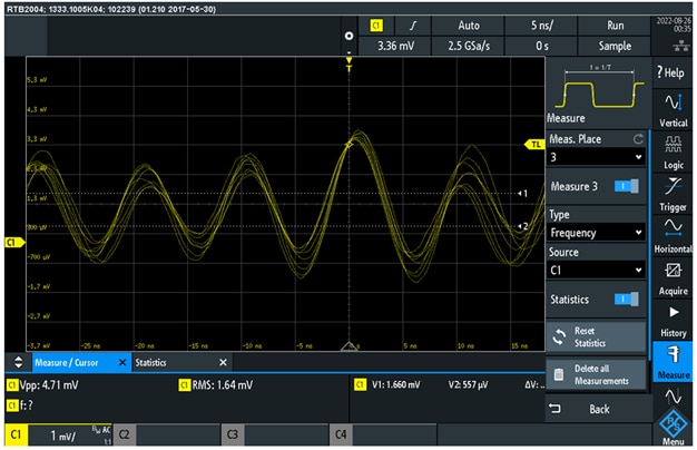
To further investigate the oscillatory behavior, I have enabled the FFT measurement function of the RTB2004 oscilloscope, as shown in the figure below:

We can see in the FFT plot a resonance spur at 103.8MHz and a second one around 200MHz that is probably the harmonic of the first resonance peak. The resonance peak at 103.8MHz accounts for most of the pk-pk noise. So I asked myself: is this oscillation on the output of the NGL201 voltage? To answer this question I have turned the power ON and OFF on the NGL201 power supply. In both cases, NGL201 with the power ON and with the power OFF the resonance spur at 100MHz was still present as shown in the figure below:

The pk-pk mean value is now 2.35mV with power ON and 2.33mV with power OFF. The rms noise is 0.890mV with power ON and 0.796mV with power OFF. If I subtract now the noise with power ON from the noise with power OFF as rms values and I then multiply by 6 to get the equivalent pk-pk noise contribution of the NGL201 power supply I calculate:
V_rms = SQRT( (0.890)^2 – (0.796)^2)= 0.398mV Now if I multiply by 6 to get the pk-pk value: V_pk_pk= 6* 0.398mV=2.38mV This value is more in line with the spec of 2mV pk-pk.
So I have learned in this experiment that the measurement fixture may have a significant impact in the measured noise and ripple. The coupling from the lab environment (primarily electromagnetic fields) can alter the measurement to values much higher than the actual levels.
2. Recovery Time
This set of experiments evaluate the NGL201 recovery time. The recovery time characterizes how fast a power supply responds to a step in the load current. Here is the definition shown in the NGL201 datasheet:

The NGL201 power supply has two settings for the transient response: “normal” and “fast” transient response, so I have evaluated the recovery time for each of these settings.

For the measurement setup I needed a load that can switch On and OFF periodically, so that I could use and oscilloscope to probe the output voltage and to measure the recovery time. I decided to use an R&S NGU401 SMU as load, which I have programmed as current load that switches every 1s between 1mA and 3A. This setup is shown in the figure below:

The NGL201 was configured in normal and fast transient modes. The output voltage has been measured with a R&S RBT2004 oscilloscope. The four waveforms corresponding to rising edge, falling edge, and each for fast transient response and normal transient response are shown in the figure below:
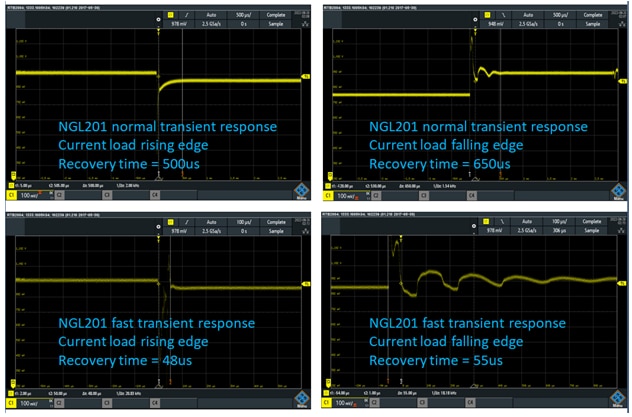
In the normal transient response the recovery time is much longer than the 30us spec. For the current load falling edge I have included the ringing in the probed recovery time. For the fast transient mode the recovery time is closer to 30us spec but still higher. In this case I didn’t include the ringing. Further investigation of the measurement setup and settings could not explain why I am seeing longer recovery time than the specifications.
3. Programmable Source Resistance
The NGL201 power supply has a function that can adjust the source resistance, which can be seen as a resistor in series with an ideal voltage source. The resistor value can be adjusted from 0 to 10kOHms based on the datasheet specifications. This section will cover my experiments focused on adjusting the source resistance of the NGL201 power supply. The adjustment can be accessed from the “Channel” settings menu:

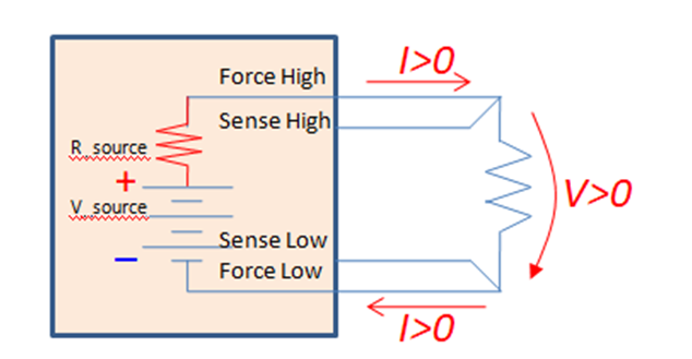
The functionality of adjusting the output impedance can be viewed as adding a series resistor to an ideal voltage source. So the programmed voltage on the power supply is the voltage of the ideal voltage source and the actual voltage that is at the power supply terminals is lower by the V=IR drop on this added source resistance. The following figure illustrates this model:
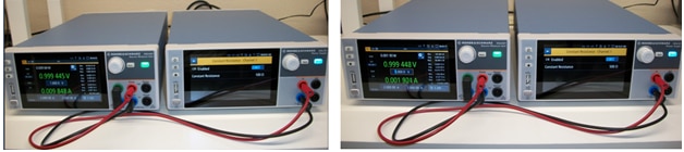
To evaluate how the NGL201 has implemented this function I have built the setup shown in the following figure and I have chosen three values for the programmed output impedance: 0 Ohms, 1 Ohm, and 2 Ohms. The output of the NGL201 is connected to a 2 Ohms resistor load in two and four wires configuration. For each setting of output impedance I have measured with an external DMM the voltage at the load and the voltage at the NGL201 output terminals. The figure below shows the measurements fortheNGL201 output impedance set to 2 Ohms. The programmed voltage is 1V. The upper two pictures show the 4-wire configuration and the bottom two pictures show the 2-wire configuration.

The measurement results corresponding to output impedance 0, 1, and 2 Ohms, configuration with2-wires interconnect and 4-wires interconnect are summarized in the table below:
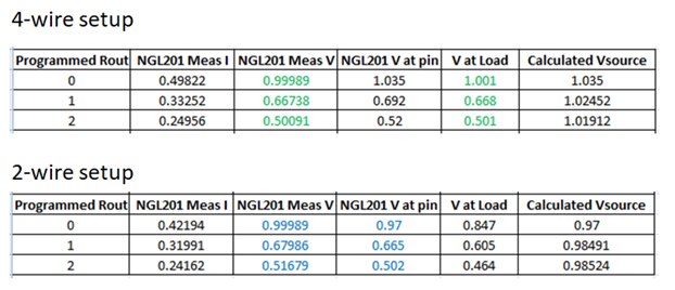
Based on these measurements, in the 4-wire configuration the NGL201 displayed voltage is the voltage at the load. The V_source seems to remain unchanged when R_source takes the values 0 Ohms, 1 Ohm, and 2 Ohms. It is interesting what voltage reference is used by the voltage regulator control loop since the NGL201 power supply does not know what is the load value. The programmed value is 1V so is it 1V used as a reference for the control loop? The sense lines probe the load voltage, which is around 0.5V for R_load=2 Ohms and R_source = 2 Ohms, so does the control loop scale up the sense lines measurement to 1V so that it can be compared with the programmed 1V?
In the 2-wire configuration is looks like the NGL201 measured voltage wants to reflect the voltage at the output pins; however, the measured values with a DMM show quite a significant difference. So I assume that the displayed voltage represents some internal voltage on the NGL201 output path (because the displayed voltage is a bit higher than the voltage at the output pins)
4. Arbitrary Waveform Generation
The NGL201 can be programmed to generate arbitrary waveforms on the output voltage and current (both when operating as voltage source or as current source).
The arbitrary waveforms can be defined using the waveform generator function available in the settings menu. The waveform is defined as piecewise linear function with a choice of interpolation (ramp) or raw square wave transitions. Here is an example for generating a triangular voltage waveform (checking interpolation box makes the transitions in the form of ramps).
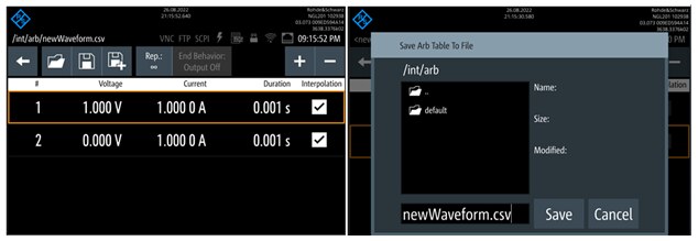
After defining the piecewise linear function the waveform needs to be saved, as shown in the right side screen capture. The saved file is then recalled in the channel settings when enabling the arbitrary waveform mode:

The following figure shows two waveforms measured with the RTB2004 oscilloscope at the load (the load is the same 2 Ohms resistor that I have used in the previous sections measurements):

The measured waveforms reflect the expected voltage and time values as programmed. The square wave signal shows a RC low pass type variation on both rising and falling edges.
5. Electronic Load
The NGL201 can be programmed as electronic load in three configurations: constant voltage, constant current, and constant resistance. The voltage and current loads have been seen in the previous sections, so in this section I will look in more details at the constant resistance mode.
Constant Resistance Mode
The NGL201 power supply can be configured to function as a resistor load, and this set of experiments have been focused on evaluating this function. The experiment setup includes the NGL201 power supply connected as the load to a NGU401 SMU, which is configured as power supply.
The resistor load has been programmed to the following values: 1, 10, 100, 200, 300, 500, 800, 900, 1000, 1100, 1200, 5000, and 10000 Ohms. For each of these values the voltage and current have been measured and the load resistance has been calculated. The experimental setup is shown in the following figures:


The measured values and calculated load resistance are summarized in the table below:

We can see in the table and on the graph that the load resistance is limited at 1kOhm. When the resistance is programmed above 1kOhm, on the spec range 1kOhm to 10kOhms, the actual load resistance of the NGL201 is 1kOhm.
I wanted to make sure that I didn’t miss anything in this experiment setup and I decided to add an external current measure instrument and to repeat the measurements above 1kOhm. Since my Fluke DMM has the current measure fuse burnt these days (Who didn’t burn the DMM current measure fuse yet? J ), I have found a good opportunity to feature in these measurements my very first multimeter instrument that my parents bought me while I was in middle school back in 1970’s when they realized that I am so passionate for electronics. The screen glass got cracked recently at the last move, but the instrument still functions. The reading accuracy is not the same as a DMM but for this troubleshooting experiment it is good enough.
Here are the readings for the NGL201 programmed to 800, 900, 5000, and10000 Ohms:


The multimeter measured current values agree with the current values displayed by the NGU401 and confirm that the actual current flowing through the circuit when NGL201 is programmed at 5000 and 10000 Ohms are the current values that correspond to the 1kOHm load resistance not 5kOHms and respectively 10kOhms. So this second part of the experiment confirms that the NGL201 cannot have a load resistance higher than 1kOhm.
This is the second update on this roadtest review work. I will come back with a new update as soon as I get more work done.
Best Wishes,
Cosmin

