


Part 3 – RoadTest Rohde & Schwarz NGL201 Power Supply
This is the third blog post in a series that will cover my work for road testing the NGL201 power supply. Part 1 has been posted at this link: (+) Part 1 – RoadTest Rohde & Schwarz NGL201 Power Supply - Cosmin Iorga's Blog - Personal Blogs - element14 Community, part 2 at this link:(+) Part 2 – RoadTest Rohde & Schwarz NGL201 Power Supply - Cosmin Iorga's Blog - Personal Blogs - element14 Community, and this is part will cover more measurement experiments and applications experiments with the NGL201 power supply.
1. Recovery Time (Additional Experiments)
The previous experiments that evaluated the NGL201 recovery time showed a much higher recovery time than the specifications, so I decided to try a different test setup to measure the recovery time. The recovery time characterizes how fast a power supply responds to a step in the load current, and it is specified as <30us for NGL201 power supply.
The NGL201 power supply has two settings for the transient response: “normal” and “fast” transient response, so I have evaluated the recovery time for each of these settings.
In the previous measurements I have used a R&S NGU401 SMU to generate a current load pulse for the NGL201 power supply, and then I measured the transient voltage variations caused by the current rise and fall time transitions. With this setup there were two instruments involved and I couldn’t tell how much each instrument contributes to the measured recovery time. In this experiment I am using an FPGA to create a current load pulse. The FPGA is programmed with an IP named “PowerLoad” that makes it draw a constant or pulse current from its power supply. This PowerLoad IP is intended for FPGAs to test their power supplies on the PCB or in the system. In this case I have powered up the FPGA from the NGL201 power supply and I configured the PowerLoad IP to generate a current pulse. I have tried a few settings for magnitude 0.5A and 1A and for frequency 500Hz and 1kHz. Additionally, I have run the same experiment on the NGL201 power supply and on the NGU401 SMU. The testbench setup is shown in the figure below:
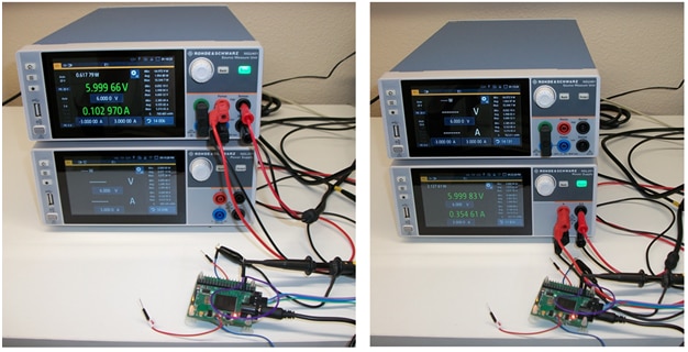
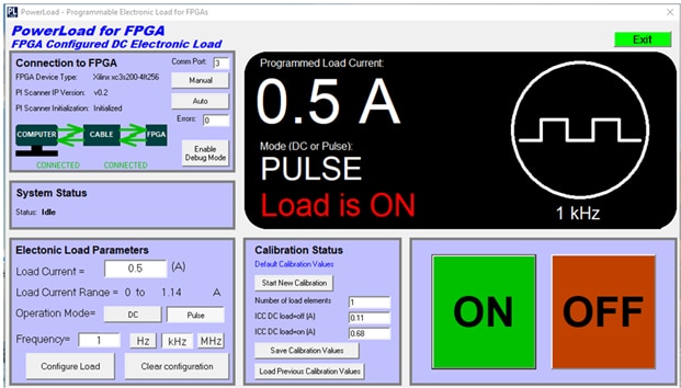
The FPGA is on the PCB which is powered from the NGU401 in the left side picture and from the NGL201 in the right side picture. The PowerLoad software application was running on a computer, and it is shown in the screenshot below:
The voltage was probed at the sense lines connection to the FPGA in the power distribution network using a R&S RTB2004 oscilloscope. The measured waveforms are shown in the figure below:
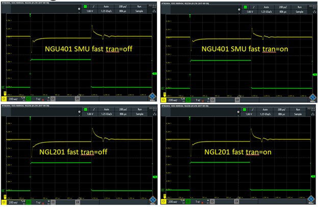
These measurements correspond to 0.5A current pulse and the NGL201/NGU401 set to fast transient enabled and disabled. The yellow trace is the measured voltage, and the green trace is a trigger signal generated by the FPGA. The trigger signal is synchronized with the current load pulse drawn by the FPGA from the power supply. The time scale is 200us per division, so we can see that the “complete” settling time is much longer than 30us for both rising and falling edges and in both NGL201 power supply and NGU401 SMU. These settling time values are similar to the previous measurement when the NGU401 SMU generated the current pulse for the NGL201 power supply. The following figure shows the recovery time for 1A magnitude of the current load pulse:
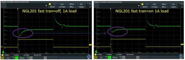
I have annotated the difference I see when the NGL201 has the fast transient On and OFF. The settling time is faster when the fast transient is ON. Also, the transient response is made of a high magnitude short pulse that is a bit hard to see in the picture followed by a slower speed “RC exponential” type section that is more visible in the picture. The oscilloscope vertical cursors are set on the short pulse (which here extends almost to the lower and upper edges of the display window), and thus they measure the settling time of the short (high magnitude) pulse. This measurement shows 34us settling time, which is in line with the NGL201 specification. Though this short pulse is followed by a long “tail” settling section of more than 200us until the voltage is fully settled.
2. Current Load Function of the NGL201 Power Supply
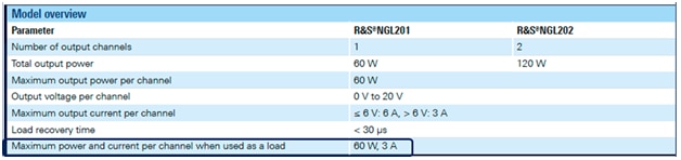
The NGL201 power supply can be configured as a current load. The maximum current load and power is defined in the specifications, as shown in the screenshot below:
In this experiment I have configured the NGL201 as current load and I have connected it to the NGU401, which is configured as a power supply. The measurement results for various current load settings are shown in the figure below:
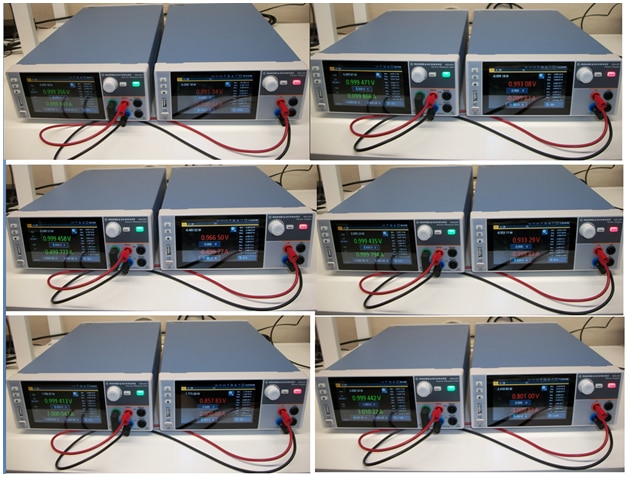
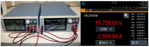
The NGL201 current load values have been set to 100mA, 500mA, 1A, 2A, and 3A. The voltage on the NGU401 has been set to 1V. This experiment has tested the current load up to the maximum 3A but it has not tested the maximum power of 60W. The following figure shows the current load measurement with the NGU401 voltage set to 20V and the NGL201 operating at close to 60W power consumption:
The current load experiments showed that the NGL201 meets the specifications as current load without any issues.
3. Battery Testing with NGL201
The NGL201 power supply can be used to measure rechargeable batteries performance. Typical battery lifetime requirements are within tens of hours (wearable) to ten years (smart sensors). In this experiment the Rohde & Schwarz power measurement tool for NGL201 will be used to capture the power consumption data and analyze it.
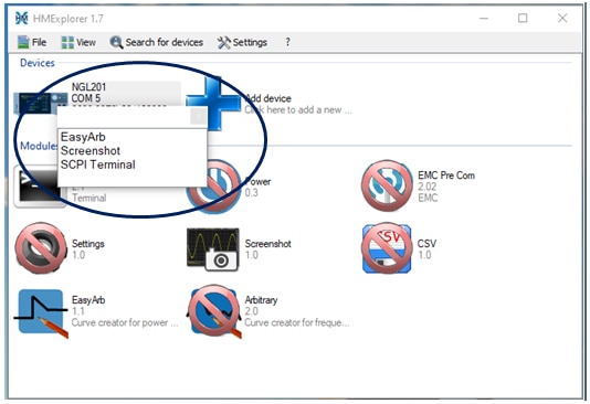
First step I wanted to do but it did not work the way I expected was to install the NGx Sweep Tool on a computer and to control the NGL201 from that application. The NGx Sweep Tool software is available to download from the Rohde & Schwarz website. There is also another application available to download named HMExplorer. So I first installed HMExplorer and that application worked well. I could communicate with the NGL201 through a USB interface:
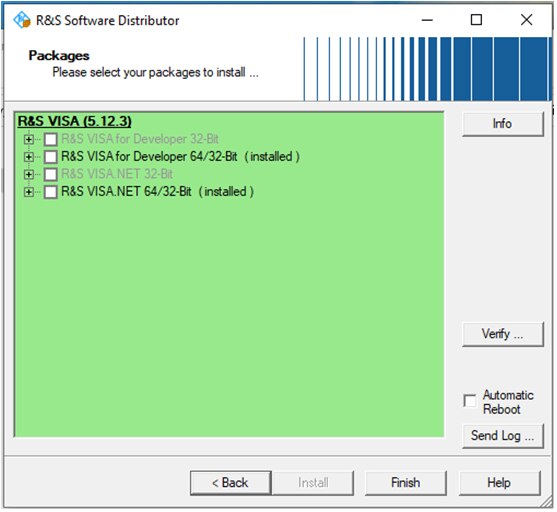
But for this experiment I needed to log measurement over time, so I downloaded and installed the NGx Sweep Tool. The R&S Visa application was also part of the installation:
The installation completed without any error; however, the NGx Sweep Tool could not connect to the NGL201 instrument. I have tried another computer with the same results and I have tried to update the NGL201 firmware but is still did not work. Here is a screenshot with the error message:
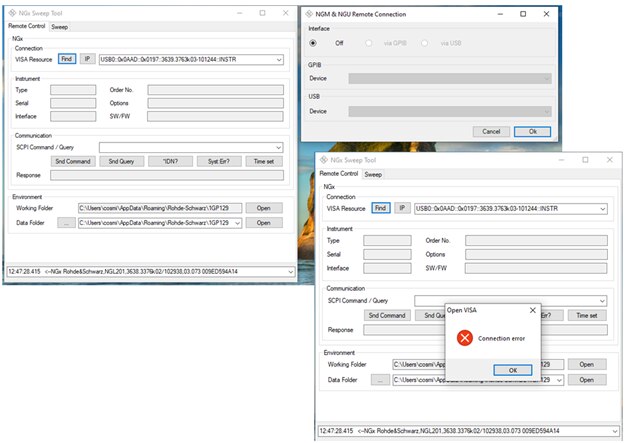
I have spent some time debugging the USB connection but I haven’t been able to fix this problem. Most probably the USB connection works because the other application, HMExplorer can communicate with the NGL201 instrument. Part of the debugging I tried to connect the NGx Sweep Tool to the NGU401 SMU, and it worked fine:
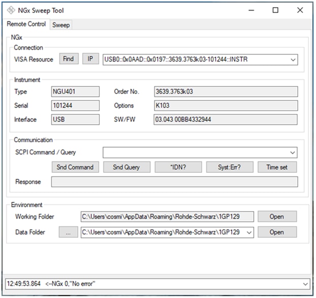
So there is some compatibility issue between the NGx Sweep Tool and my NGL201 power supply.
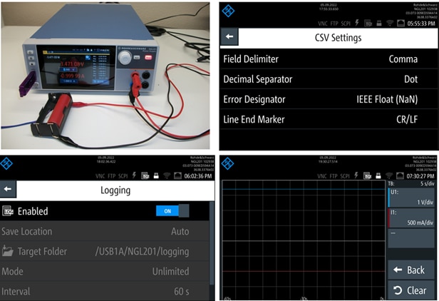
Since the application on the computer did not work, I was left with using the lodging function embedded in the NGL201 power supply. That logging function saves the measured data in a csv file. The following figure shows the setup for the .csv file and the logging parameters:
This experiment has discharged a Lithium-ion battery with a constant current using the current load function of the NGL201 and the voltage and power have been recorded using the logging function of the NGL201 instrument. The results are shown in the following figure:
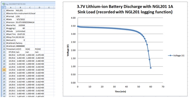
The recording time was one hour, and we can see how the battery held the voltage for about 50 minutes after which the voltage dropped rapidly.
The charging back experiment for this battery is shown in the figure below:
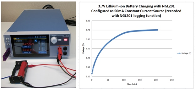
The charging current was set to 50mA and the charging time to 3.7V was around 150 minutes.
4. Measuring the Efficiency of the DCDC Converters
The NGL201 power supply can be used to measure the efficiency of the DCDC converters. The measurement needs two power supply channels, so NGL202 would be a better choice for this measurement. Since NGL201 had only one channel, I have used the NGU401 SMU as the second channel. The tested DCDC converter was one of the USB car chargers, which has 12V input from the car battery and generates 5V output for a USB powered device. The setup is shown in the figure below:
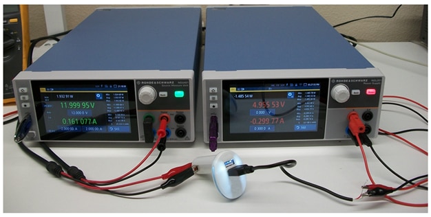
The NGU401 is configured as a 12V power supply and the NGL201 is configured as a constant current load. The measurements at 200mA current load and 1A current load are shown in the figure below:
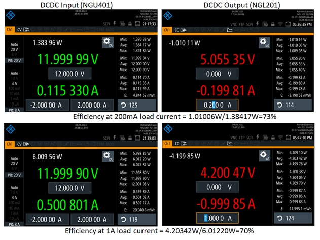
The NGL201 and NGU401 display the output power min, max, and average. Using the average values, I calculated the efficiency as 73% at 200mA load current and 70% at 1A current load, as shown in the figure.
5. Testing the Startup of DCDC Converters with the NGL201 Power Supply
The NGL201 power supply can be used to setup various waveforms for testing the startup of electronic circuits. In this experiment I have configured the NGL201 power supply to generate different slope ramp type voltages that tested the functionality and performance of a DCDC converter. In general, slower voltage ramps applied to DCC converters may create high current spikes that may damage the load circuits or the internal circuits of the DCDC converter.
The NGL201 power supply has an arbitrary function generator and also it has a ramp function. Since I have used the arbitrary waveform generator earlier in this roadtest, for this experiment I decided to use the ramp function. The Experiment setup is similar to the one used for DCDC efficiency measurement. The DCDC converter is a car charger that is powered with 12V from the NGL201 instrument and the NGU401 instrument is configured as constant current load. This setup is shown in the figure below:
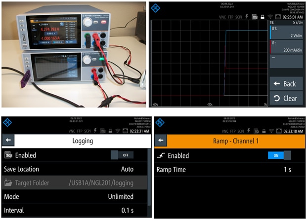
The ramp is set to one second and the logging interval to 0.1 seconds, so we expect to see 10 measurement point along the ramping. The voltage and current variation with time are displayed on the graphic view function of the NGL201 power supply (the blue trace is voltage, and the red trace is current). Notice that there is a spike overshoot in current during the voltage ramping. The spike magnitude is about twice the final value. The voltage and current waveforms have been also recorded by the logging function and they have been saved as a csv file on the memory stick. The following figure shows the logged data plotted in a Microsoft Excel spreadsheet:
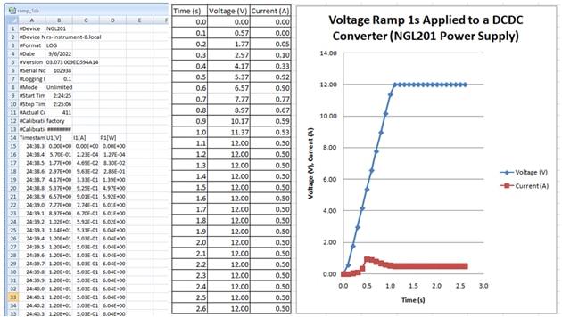
The logged values are time, voltage, current, and power. The graph shows the voltage ramp and the current during this ramp. The overshoot current spike happens during the first half of the ramp.
I then increased the ramp length to 10 seconds, and I have setup the load current to 0.5A. The experiment setup and measurement results are shown in the figure below:
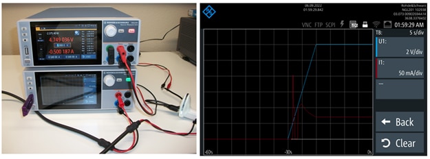
The longer ramp time has generated two current spikes: a very sharp one that falls back to zero followed by a “smoother” one which settles at the steady state current consumption level. Next I increased the current load to 1A, and I performed the same measurement:
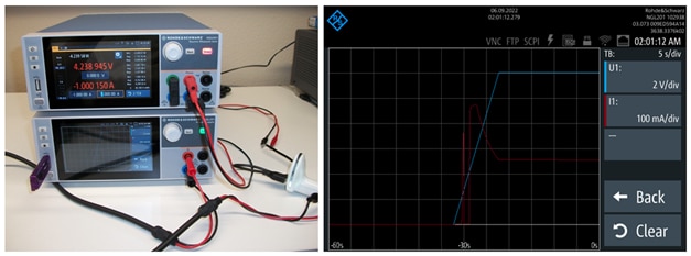
There are still two current overshoot spikes. The first one has similar shape and amplitude like for the 0.5A current load but the second one has a much higher magnitude. It looks to me that the magnitude of the second overshot scales with the programmed DC current load level.
This concludes the third update and the roadtest review experiments. Over the past few weeks, I had the opportunity to roadtest the Rohde & Schwarz NGL201 instrument. I enjoyed this activity and I want to thank Rohde & Schwarz and Element 14 for selecting me as the road testers for this instrument. During these weeks I have run multiple experiments and I have performed multiple measurements with the NGL201 power supply. From all this work I am impressed with the quality and performance of the NGL201 instrument. The front panel display is crisply sharp and clear, and the instrument control is easy and intuitively straight forward. There were a few performance parameters that I could not correlate with the specifications and some software compatibility problems that I have described above. My overall conclusion is that the NGL201 power supply is a great instrument made so that it gives me the impression of a solid, high quality, and reliable test equipment. I feel fortunate for having the opportunity to explore the functionality and performance of the R&S NGL201 instrument through this roadtest.

