EDIT 2 Feb 2021: Added explanation for poor matching of motors
I have an ongoing project to develop a robot which will use a Raspberry Pi for the main brain and I2C communication with a microcontroller for real time activities such as PID control of motor speed. Links are given at the bottom of this post describing the implementation of I2C communication between a Raspberry Pi and Arduino, and PID (only proportional and integral are used) motor control on an Arduino. Here I'll describe adding DIY rotary encoders to a tracked robot not originally so equipped.
How It Works
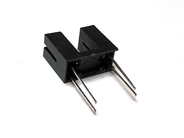
The sensor used here is the ITR9608-F, an opto-interrupter consisting of a infrared emitting diode and an NPN silicon phototransistor encased in a thermoplastic housing.
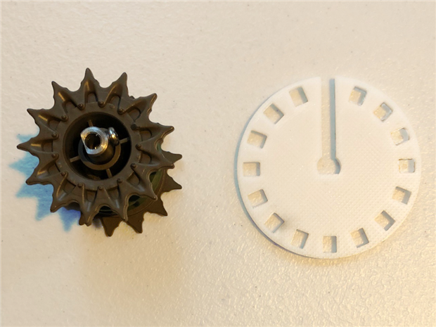
The robot did not come with encoders so a wheel with 16 equally spaced slots was designed in Fusion 360 and printed in PLA. As the openings pass through the slots in the opto-interrupter they trigger the photo-transistor and cause the sensor to output a digital high signal. When occluded the sensor outputs low. The photo below shows how the encoder wheel fits onto the tank cog. It was necessary to modify the slot at 12:00 to allow the screw to be tightened on the cog.
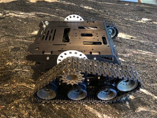
Here the encoder wheels are shown installed on the robot without the opto-interrupter in place.
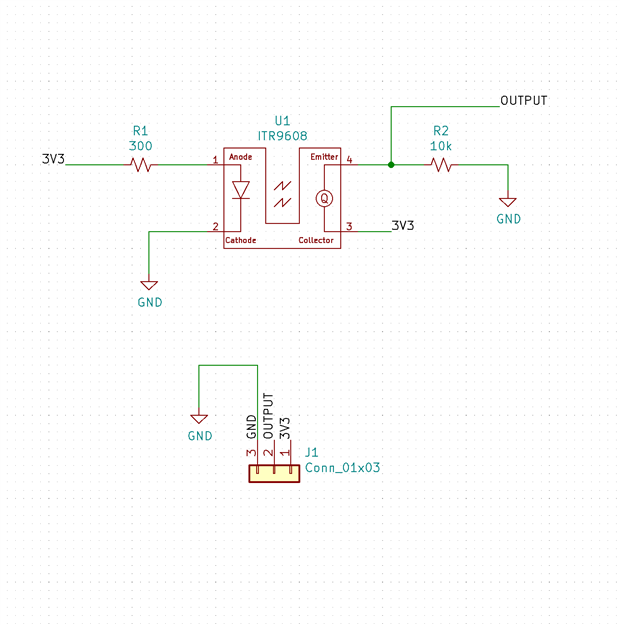
A simple circuit is used to interface the ITR9608-F opto-interrupter to the microcontroller.
Resistor R1 provides current limiting to the infrared LED. When the light from the LED is occluded by the encoder wheel resistor R2 pulls the output low. When the light from the LED can reach the phototransistor it turns on and the output is high. The circuit was built on a bit of stripboard and a 3D printed mount designed for attaching to the robot. Testing was done with the Arduino connected through a breadboard to the motor controller and the prototype encoder wheel was reprinted in black PLA although the white ones would have probably been just fine. It was a rainy day in Portland.
Testing
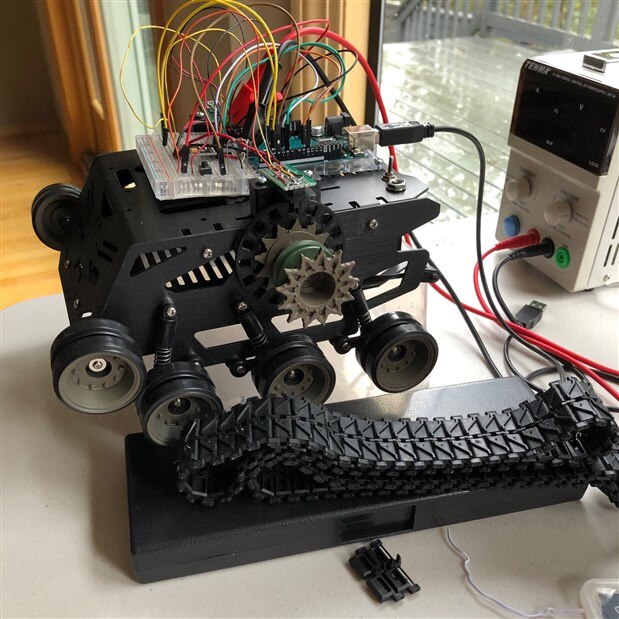
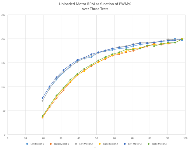
This is a new robot built from a kit (DFRobot Devastator) and the motors haven't been run in. I took off the tracks and put it on a box so it couldn't go anywhere for the tests which consisted of increasing the PWM duty from 20% to 100% in steps of 3.9% with the motors unloaded. Three runs were made and are shown plotted below.
The importance of PID control with feedback for good motor control is apparent:
- Responses between the two motors differ
- Responses are not linear
- Responses vary somewhat between runs
We could expect additional variation to occur as the motors experience different loadings, the battery voltage output changes, the motors age, and so.
EDIT 2 Feb 2021: The poor matching of the motors is caused by the Arduino Uno used during these tests putting out different PWM frequencies (but not duty) during the tests shown in the plot above. See comments below for further detail. Performance improves greatly when two output pins using the same PWM output frequencies are used.
Sensor PCBs
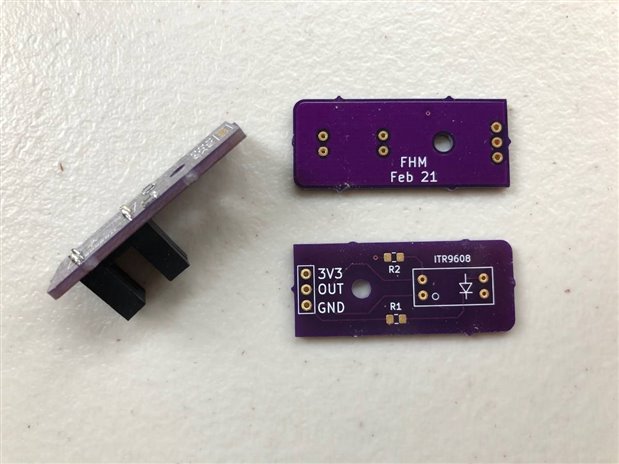
I suppose I got in a hurry with the PCBs. Electrically they are OK but I forgot to move the footprint I had crafted to the back side of the board. As a result the 0805 surface mount resistors press against the mounts for the sensors so I will reprint the mounts with little indentations or drill indentations to accept them. I installed the sensor below backwards before figuring out what I had done wrong. Doh!
Conclusion
I'll modify the KiCad files for the sensor PCB but use the ones I have for now. The next step is to design mounts for the microcontroller, Raspberry Pi, batteries, a PCB for power distribution and the motor controller, and so on. The plan is to have something working by next summer for Robot Summer Camp with the grandkids. Thanks for reading - comments and thoughts for improvement are always welcome.
Past Links to this Project
Simple Arduino DC Motor Control with Encoder, Part 1


Top Comments
-

three-phase
-
Cancel
-
Vote Up
+2
Vote Down
-
-
Sign in to reply
-
More
-
Cancel
-

fmilburn
in reply to three-phase
-
Cancel
-
Vote Up
+3
Vote Down
-
-
Sign in to reply
-
More
-
Cancel
-

three-phase
in reply to fmilburn
-
Cancel
-
Vote Up
+3
Vote Down
-
-
Sign in to reply
-
More
-
Cancel
Comment-

three-phase
in reply to fmilburn
-
Cancel
-
Vote Up
+3
Vote Down
-
-
Sign in to reply
-
More
-
Cancel
Children