element14 Community
element14 Community
    Register Log In
  • Site
  • Search
  • Log In Register
  • About Us
  • Community Hub
    Community Hub
    • What's New on element14
    • Feedback and Support
    • Benefits of Membership
    • Personal Blogs
    • Members Area
    • Achievement Levels
  • Learn
    Learn
    • Ask an Expert
    • eBooks
    • element14 presents
    • Learning Center
    • Tech Spotlight
    • STEM Academy
    • Webinars, Training and Events
    • Learning Groups
  • Technologies
    Technologies
    • 3D Printing
    • FPGA
    • Industrial Automation
    • Internet of Things
    • Power & Energy
    • Sensors
    • Technology Groups
  • Challenges & Projects
    Challenges & Projects
    • Design Challenges
    • element14 presents Projects
    • Project14
    • Arduino Projects
    • Raspberry Pi Projects
    • Project Groups
  • Products
    Products
    • Arduino
    • Avnet Boards Community
    • Dev Tools
    • Manufacturers
    • Multicomp Pro
    • Product Groups
    • Raspberry Pi
    • RoadTests & Reviews
  • Store
    Store
    • Visit Your Store
    • Choose another store...
      • Europe
      •  Austria (German)
      •  Belgium (Dutch, French)
      •  Bulgaria (Bulgarian)
      •  Czech Republic (Czech)
      •  Denmark (Danish)
      •  Estonia (Estonian)
      •  Finland (Finnish)
      •  France (French)
      •  Germany (German)
      •  Hungary (Hungarian)
      •  Ireland
      •  Israel
      •  Italy (Italian)
      •  Latvia (Latvian)
      •  
      •  Lithuania (Lithuanian)
      •  Netherlands (Dutch)
      •  Norway (Norwegian)
      •  Poland (Polish)
      •  Portugal (Portuguese)
      •  Romania (Romanian)
      •  Russia (Russian)
      •  Slovakia (Slovak)
      •  Slovenia (Slovenian)
      •  Spain (Spanish)
      •  Sweden (Swedish)
      •  Switzerland(German, French)
      •  Turkey (Turkish)
      •  United Kingdom
      • Asia Pacific
      •  Australia
      •  China
      •  Hong Kong
      •  India
      •  Korea (Korean)
      •  Malaysia
      •  New Zealand
      •  Philippines
      •  Singapore
      •  Taiwan
      •  Thailand (Thai)
      • Americas
      •  Brazil (Portuguese)
      •  Canada
      •  Mexico (Spanish)
      •  United States
      Can't find the country/region you're looking for? Visit our export site or find a local distributor.
  • Translate
  • Profile
  • Settings
Personal Blogs
  • Community Hub
  • More
Personal Blogs
Frank Milburn's Blog Testing DC Motors on a Robot with DIY Rotary Encoders
  • Blog
  • Documents
  • Mentions
  • Sub-Groups
  • Tags
  • More
  • Cancel
  • New
  • Share
  • More
  • Cancel
Group Actions
  • Group RSS
  • More
  • Cancel
Engagement
  • Author Author: fmilburn
  • Date Created: 1 Mar 2021 5:30 AM Date Created
  • Views 8005 views
  • Likes 13 likes
  • Comments 23 comments
  • motor control
  • robot
  • encoder
  • rotary encoder
  • arduino
Related
Recommended

Testing DC Motors on a Robot with DIY Rotary Encoders

fmilburn
fmilburn
1 Mar 2021

EDIT  2 Feb 2021:  Added explanation for poor matching of motors


I have an ongoing project to develop a robot which will use a Raspberry Pi for the main brain and I2C communication with a microcontroller for real time activities such as PID control of motor speed.  Links are given at the bottom of this post describing the implementation of I2C communication between a Raspberry Pi and Arduino, and PID (only proportional and integral are used) motor control on an Arduino.  Here I'll describe adding DIY rotary encoders to a tracked robot not originally so equipped.

image

How It Works


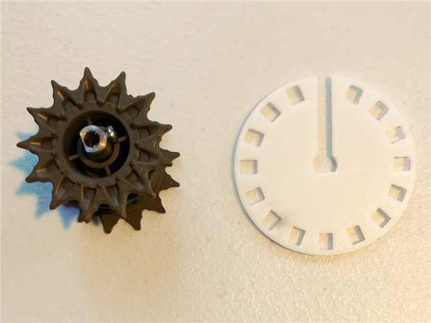
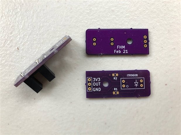
The sensor used here is the ITR9608-F, an opto-interrupter consisting of a infrared emitting diode and an NPN silicon phototransistor encased in a thermoplastic housing.

image

The robot did not come with encoders so a wheel with 16 equally spaced slots was designed in Fusion 360 and printed in PLA.  As the openings pass through the slots in the opto-interrupter they trigger the photo-transistor and cause the sensor to output a digital high signal.  When occluded the sensor outputs low.  The photo below shows how the encoder wheel fits onto the tank cog.  It was necessary to modify the slot at 12:00 to allow the screw to be tightened on the cog.

image

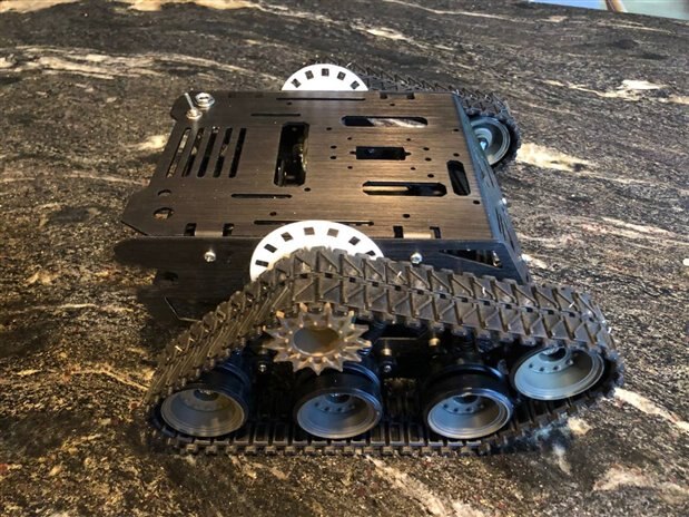
Here the encoder wheels are shown installed on the robot without the opto-interrupter in place.

image

A simple circuit is used to interface the ITR9608-F opto-interrupter to the microcontroller.

image

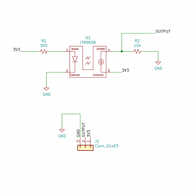
Resistor R1 provides current limiting to the infrared LED.  When the light from the LED is occluded by the encoder wheel resistor R2 pulls the output low.  When the light from the LED can reach the phototransistor it turns on and the output is high.  The circuit was built on a bit of stripboard and a 3D printed mount designed for attaching to the robot.  Testing was done with the Arduino connected through a breadboard to the motor controller and the prototype encoder wheel was reprinted in black PLA although the white ones would have probably been just fine.  It was a rainy day in Portland.

image

Testing


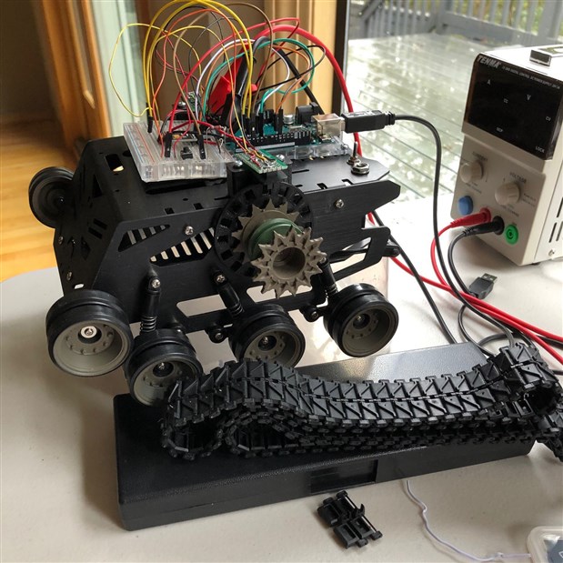
This is a new robot built from a kit (DFRobot Devastator) and the motors haven't been run in.  I took off the tracks and put it on a box so it couldn't go anywhere for the tests which consisted of increasing the PWM duty from 20% to 100% in steps of 3.9% with the motors unloaded.  Three runs were made and are shown plotted below.

image

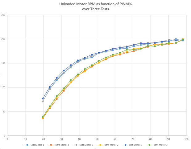
The importance of PID control with feedback for good motor control is apparent:

  • Responses between the two motors differ
  • Responses are not linear
  • Responses vary somewhat between runs


We could expect additional variation to occur as the motors experience different loadings, the battery voltage output changes, the motors age, and so.


EDIT  2 Feb 2021:  The poor matching of the motors is caused by the Arduino Uno used during these tests putting out different PWM frequencies (but not duty) during the tests shown in the plot above.  See comments below for further detail.  Performance improves greatly when two output pins using the same PWM output frequencies are used.


Sensor PCBs


I suppose I got in a hurry with the PCBs.  Electrically they are OK but I forgot to move the footprint I had crafted to the back side of the board.  As a result the 0805 surface mount resistors press against the mounts for the sensors so I will reprint the mounts with little indentations or drill indentations to accept them.  I installed the sensor below backwards before figuring out what I had done wrong.  Doh!


image

Conclusion


I'll modify the KiCad files for the sensor PCB but use the ones I have for now.  The next step is to design mounts for the microcontroller, Raspberry Pi, batteries, a PCB for power distribution and the motor controller, and so on.  The plan is to have something working by next summer for Robot Summer Camp with the grandkids.  Thanks for reading - comments and thoughts for improvement are always welcome.


Past Links to this Project


Simple Arduino DC Motor Control with Encoder, Part 1

Simple Arduino DC Motor Control with Encoder, Part 2

Raspberry Pi and Arduino I2C Communication

  • Sign in to reply

Top Comments

  • neilk
    neilk over 4 years ago +4
    Nice post, Frank. Very interesting to see the different behaviour of the 2 motors; without some sort of balancing - PI D - would be difficult to get this beast to travel in a straight line. Neil
  • fmilburn
    fmilburn over 4 years ago in reply to genebren +4
    OK, ran it again and then swapped the connections to the motor controller and got the following counts (settings slightly different than yesterday): Original Duty Right Left 49% 77 91 98% 122 121 Swapped…
  • shabaz
    shabaz over 4 years ago +3
    Hi Frank, This is really nice to see the custom work for the encoders. I worked on a transceiver project where the engineers created a similar solution for a custom frequency control dial. It was super…
Parents
  • dubbie
    dubbie over 4 years ago

    Frank,


    I was looking at some similar detectors for mobile robots only this morning so your Blog was of great interest. I am interested to know how you arranged the sensor to be at the correct height so that there isn't any variation in the alignment of the slots in the disk to the detection area of the sensor - or is there sufficient tolerance to take care of any variations? Also, do you think it would be possible to create a disk with more slots? Also, also, doesn't the infrared just shine through the plastic of the disc whether there is a slot or not? I've tried using 3D printed parts for optical interruption and it didn't work that well - just diffused everything into a blur.


    Dubbie

    • Cancel
    • Vote Up +3 Vote Down
    • Sign in to reply
    • More
    • Cancel
Comment
  • dubbie
    dubbie over 4 years ago

    Frank,


    I was looking at some similar detectors for mobile robots only this morning so your Blog was of great interest. I am interested to know how you arranged the sensor to be at the correct height so that there isn't any variation in the alignment of the slots in the disk to the detection area of the sensor - or is there sufficient tolerance to take care of any variations? Also, do you think it would be possible to create a disk with more slots? Also, also, doesn't the infrared just shine through the plastic of the disc whether there is a slot or not? I've tried using 3D printed parts for optical interruption and it didn't work that well - just diffused everything into a blur.


    Dubbie

    • Cancel
    • Vote Up +3 Vote Down
    • Sign in to reply
    • More
    • Cancel
Children
  • fmilburn
    fmilburn over 4 years ago in reply to dubbie

    Hi Dubbie,


    Glad the blog may be of use to you.  To get the sensor at the right height I made the encoder wheel diameter large enough to project above the track mechanism.  Then a block which attaches to the robot and holds the sensor in place above the encoder wheel at the right height was made in the 3D printer.  The opto-interrupter fits through the hole in the block and the PCB is held in place with a screw (screw not in place in the photo).  In my case the block can be slid along a track in the robot to properly position it horizontally as well.

    image

    image

    The sensors can be bought with different dimensions which must be taken into account.  Below are the dimensions for mine taken from the Everlight datasheet.

    image

    Regarding the encoder wheel itself, what I should do is make the slots "keystone" shaped with equally shaped spokes in between but that is probably using a micrometer to measure the brick in my case.  I may do go back and do that anyway now that you have noticed it :-). 


    It is definitely possible to make a disk with more slots.   I have seen some smaller diameter encoders in inkjet printers for example with many more slots.  In my case I needed to fit a screwdriver down one of the slots as explained in the text so that set the width of the slot.  There will be some point at which the light is getting through two slots to the phototransistor.  It might be possible to get that from the datasheet, else it could be done experimentally.  Also remember that the sensor can trigger on both rising and falling edges which increases resolution.


    I have not had a problem with infrared getting through the PLA on these sensors.  In fact, they will work by just occluding the slot with relatively thin paper instead of PLA.  Note that I did reprint the encoder wheels in black PLA as noted in the text which should reduce transmission through the PLA but I don't think it was necessary.  If you do run into problems you could try using a higher resistance current limiting resistor to the LED.


    Hope this helps!


    Frank

    • Cancel
    • Vote Up +3 Vote Down
    • Sign in to reply
    • More
    • Cancel
  • dubbie
    dubbie over 4 years ago in reply to fmilburn

    Frank,


    Thanks very much. Lots of good ideas. Not sure why I didn't think of them myself - they seem so obvious now. Maybe I'll have a go at using this sensor sometime.


    Dubbie

    • Cancel
    • Vote Up +2 Vote Down
    • Sign in to reply
    • More
    • Cancel
element14 Community

element14 is the first online community specifically for engineers. Connect with your peers and get expert answers to your questions.

  • Members
  • Learn
  • Technologies
  • Challenges & Projects
  • Products
  • Store
  • About Us
  • Feedback & Support
  • FAQs
  • Terms of Use
  • Privacy Policy
  • Legal and Copyright Notices
  • Sitemap
  • Cookies

An Avnet Company © 2025 Premier Farnell Limited. All Rights Reserved.

Premier Farnell Ltd, registered in England and Wales (no 00876412), registered office: Farnell House, Forge Lane, Leeds LS12 2NE.

ICP 备案号 10220084.

Follow element14

  • X
  • Facebook
  • linkedin
  • YouTube