element14 Community
element14 Community
    Register Log In
  • Site
  • Search
  • Log In Register
  • Community Hub
    Community Hub
    • What's New on element14
    • Feedback and Support
    • Benefits of Membership
    • Personal Blogs
    • Members Area
    • Achievement Levels
  • Learn
    Learn
    • Ask an Expert
    • eBooks
    • element14 presents
    • Learning Center
    • Tech Spotlight
    • STEM Academy
    • Webinars, Training and Events
    • Learning Groups
  • Technologies
    Technologies
    • 3D Printing
    • FPGA
    • Industrial Automation
    • Internet of Things
    • Power & Energy
    • Sensors
    • Technology Groups
  • Challenges & Projects
    Challenges & Projects
    • Design Challenges
    • element14 presents Projects
    • Project14
    • Arduino Projects
    • Raspberry Pi Projects
    • Project Groups
  • Products
    Products
    • Arduino
    • Avnet Boards Community
    • Dev Tools
    • Manufacturers
    • Multicomp Pro
    • Product Groups
    • Raspberry Pi
    • RoadTests & Reviews
  • About Us
  • Store
    Store
    • Visit Your Store
    • Choose another store...
      • Europe
      •  Austria (German)
      •  Belgium (Dutch, French)
      •  Bulgaria (Bulgarian)
      •  Czech Republic (Czech)
      •  Denmark (Danish)
      •  Estonia (Estonian)
      •  Finland (Finnish)
      •  France (French)
      •  Germany (German)
      •  Hungary (Hungarian)
      •  Ireland
      •  Israel
      •  Italy (Italian)
      •  Latvia (Latvian)
      •  
      •  Lithuania (Lithuanian)
      •  Netherlands (Dutch)
      •  Norway (Norwegian)
      •  Poland (Polish)
      •  Portugal (Portuguese)
      •  Romania (Romanian)
      •  Russia (Russian)
      •  Slovakia (Slovak)
      •  Slovenia (Slovenian)
      •  Spain (Spanish)
      •  Sweden (Swedish)
      •  Switzerland(German, French)
      •  Turkey (Turkish)
      •  United Kingdom
      • Asia Pacific
      •  Australia
      •  China
      •  Hong Kong
      •  India
      •  Korea (Korean)
      •  Malaysia
      •  New Zealand
      •  Philippines
      •  Singapore
      •  Taiwan
      •  Thailand (Thai)
      • Americas
      •  Brazil (Portuguese)
      •  Canada
      •  Mexico (Spanish)
      •  United States
      Can't find the country/region you're looking for? Visit our export site or find a local distributor.
  • Translate
  • Profile
  • Settings
Personal Blogs
  • Community Hub
  • More
Personal Blogs
Gene Breniman's Blog Hand soldering a VQFN24 part to a PCB - part 2
  • Blog
  • Documents
  • Mentions
  • Sub-Groups
  • Tags
  • More
  • Cancel
  • New
  • Share
  • More
  • Cancel
Group Actions
  • Group RSS
  • More
  • Cancel
Engagement
  • Author Author: genebren
  • Date Created: 1 Aug 2022 7:10 PM Date Created
  • Views 2202 views
  • Likes 12 likes
  • Comments 13 comments
  • VQFN24
  • soldering tips
  • 3D Printing
  • ATtiny3327
Related
Recommended

Hand soldering a VQFN24 part to a PCB - part 2

genebren
genebren
1 Aug 2022

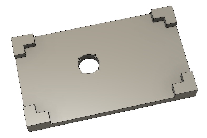
In my prior post (/members-area/personalblogs/b/gene-breniman-s-blog/posts/hand-soldering-a-vqfn24-part-to-a-pcb), I was very happy with the end result, but a little disappointed with the preciseness of the alignment of the chip on the board.  So, as I had mentioned in that blog, I decided to redesign my soldering jig, using some of the available holes (pins and mounting) to align the board on to the fixture (as opposed to the board edges). In redesigning the fixture, I first removed the four corner retainers (first image) and shrunk down the overall size to match the PCB.  I then extracted position information from my PCB design software (Eagle) for the location and sizes of the USB plug mounting holes and the three pin header on the opposite side of the PCB.  With that information I fired up Fusion360 (after renewing my license) and added two prongs (USB plug) and three square holes (header) to the fixture (second image).

image  image

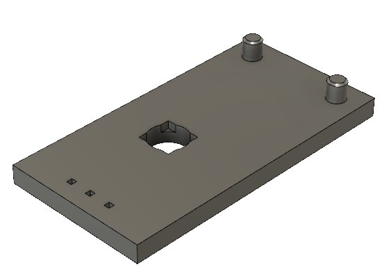
After slicing and then printing my fixture, I did a little cleanup and here is then new soldering jig:

imageimage

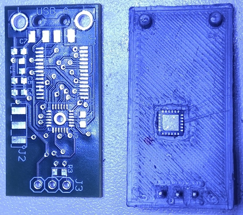
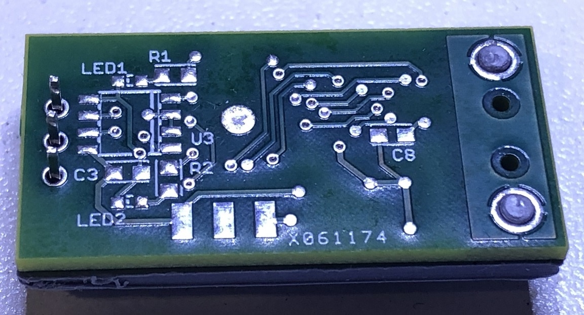
Here is an image of the PCB test loaded into the fixture (chip installed, notice the sharpie mark in the upper left hand corner to remind me of the correct chip position). 

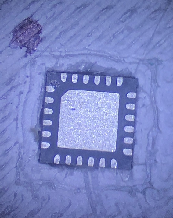
Below, we are looking through the through-hole at the exposed pad (the PCB is tilted in the board vise, under the microscope).

image

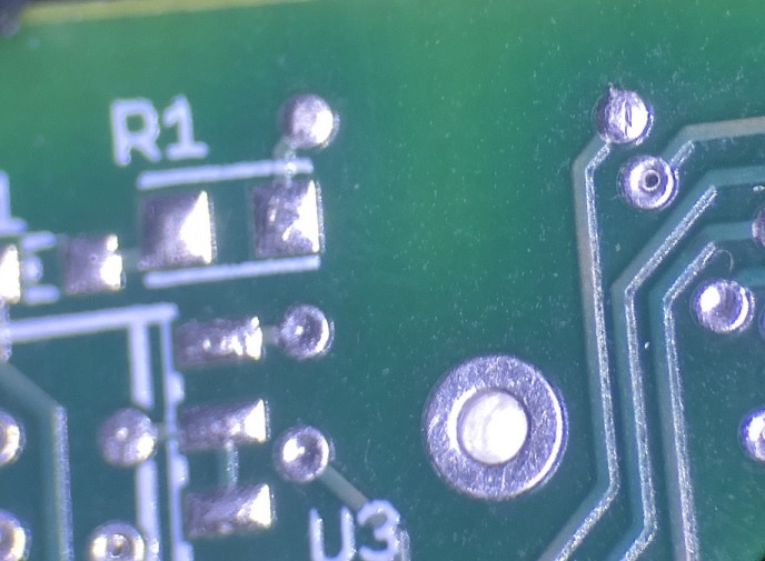
Note: the bright white spot in the center in the center of the pad is the exposed pad of the VQFN24 chip.  With the image tilted like this, zooming in allows you to see if the exposed pad is flush with the through-hole pad (now dark shadow, viewed at multiple angles.

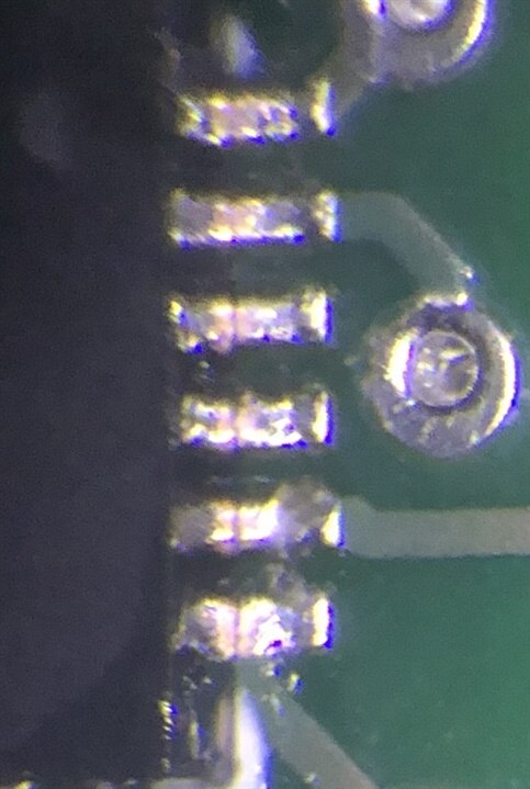
With everything looking good, I unmounted the PCB and applied flux to the exposed pad and the top of the through-hole pad and remount the PCB into the soldering jig.  I then proceeded to feed solder into the through-hole pad, moving the soldering iron tip around the hole, allowing the solder to bound to the exposed pad.  Then after allowing the solder to cool, I carefully removed the PCB from the soldering jig (while pressing on the chip top to free it from the indent).  Here are some images of the pin-to-pad alignment:

image

Here is an image of the PCB is soldering jig, after soldering to the exposed pad via the through-hole (the hole is filled, nearly flush to the surface).

imageimage

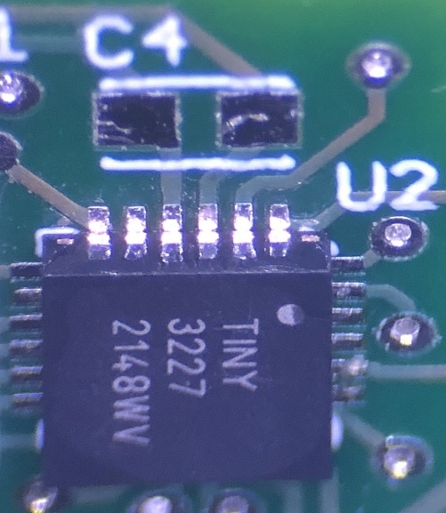
The alignment is very good (notice the longer than normal pads on the PCB, I wanted to be sure to have plenty of pad space to apply heat to while soldering).  I also verified that the chip pads were in all equally positioned to the surface of the PCB.  From there, I applied solder flux and soldered the pins by placing a small blob of solder on the first pin and carefully dragging across the remaining pins.  Some sides required a few drags to get all of the pads soldered, with not solder bridges.

Now, I need to test each of the pins to see if I have continuity and no shorts.  I will be saving that task for a while as my coordination and energy levels are a bit impaired. Yesterday I tested positive for COVID after having some cold like symptoms.  We had recently traveled, to Tacoma to visit with relatives and I am sure that the while flying (fully masked) with mostly unmasked passengers we were infected.  I am doing fine, just tired, fuzzy, coughing and congested.  My wife tested negative, so I am isolating in my office and a spare bedroom, although she is pretty sure that she is coming down with it too.  Thankfully we are both fully vaccinated and boosted (x2), so this should not be a huge problem.

  • Sign in to reply
Parents
  • Andrew J
    Andrew J over 3 years ago

    It's a great idea and the alignment is excellent.  How do you test for continuity/shorts?

    • Cancel
    • Vote Up 0 Vote Down
    • Sign in to reply
    • More
    • Cancel
Comment
  • Andrew J
    Andrew J over 3 years ago

    It's a great idea and the alignment is excellent.  How do you test for continuity/shorts?

    • Cancel
    • Vote Up 0 Vote Down
    • Sign in to reply
    • More
    • Cancel
Children
  • genebren
    genebren over 3 years ago in reply to Andrew J

    Thanks,

    Last time (prior post) I did pin to pin continuity tests (also pin to power and ground). Pin to power/ground should show a ESD diode (providing continuity) and pin to neighboring pin should eliminate any shorts.  The good news, is that most the processor pins have at least a single via on the nets, so probing is not to difficult.

    Otherwise, once I have assembled the board, I have some debug firmware the sequentially drives each pin high then low. By probing with my oscilloscope and see any shorts and/or opens.  I also have functional firmware that will also show any defects.

    • Cancel
    • Vote Up 0 Vote Down
    • Sign in to reply
    • More
    • Cancel
  • ralphjy
    ralphjy over 3 years ago in reply to genebren

    Sounds like a guy who's done a lot of ICT,  LOL!

    Maybe you need a bed of nails fixture Wink.

    • Cancel
    • Vote Up 0 Vote Down
    • Sign in to reply
    • More
    • Cancel
  • genebren
    genebren over 3 years ago in reply to ralphjy

    Funny you should mention that.  I used to design ICT test systems (hardware and software) for Teradyne (formerly Zenthel), so I do have a lot of experience with all of the concepts. I have been working on designing a bed of nails fixture for one of my higher volume products (100+ a year), but I plan on using for more of a function test (I just want to the simple connectivity afforded by the bed of nails).

    • Cancel
    • Vote Up 0 Vote Down
    • Sign in to reply
    • More
    • Cancel
  • Andrew J
    Andrew J over 3 years ago in reply to genebren

    I guess I was wondering whether you use continuity or resistance on your multimeter, what voltage it generates.  Because if you do it, then I’m going to assume it’s safe for the device in the face of shorts which is something I always worry about.

    • Cancel
    • Vote Up 0 Vote Down
    • Sign in to reply
    • More
    • Cancel
element14 Community

element14 is the first online community specifically for engineers. Connect with your peers and get expert answers to your questions.

  • Members
  • Learn
  • Technologies
  • Challenges & Projects
  • Products
  • Store
  • About Us
  • Feedback & Support
  • FAQs
  • Terms of Use
  • Privacy Policy
  • Legal and Copyright Notices
  • Sitemap
  • Cookies

An Avnet Company © 2025 Premier Farnell Limited. All Rights Reserved.

Premier Farnell Ltd, registered in England and Wales (no 00876412), registered office: Farnell House, Forge Lane, Leeds LS12 2NE.

ICP 备案号 10220084.

Follow element14

  • X
  • Facebook
  • linkedin
  • YouTube