element14 Community
element14 Community
    Register Log In
  • Site
  • Search
  • Log In Register
  • About Us
  • Community Hub
    Community Hub
    • What's New on element14
    • Feedback and Support
    • Benefits of Membership
    • Personal Blogs
    • Members Area
    • Achievement Levels
  • Learn
    Learn
    • Ask an Expert
    • eBooks
    • element14 presents
    • Learning Center
    • Tech Spotlight
    • STEM Academy
    • Webinars, Training and Events
    • Learning Groups
  • Technologies
    Technologies
    • 3D Printing
    • FPGA
    • Industrial Automation
    • Internet of Things
    • Power & Energy
    • Sensors
    • Technology Groups
  • Challenges & Projects
    Challenges & Projects
    • Design Challenges
    • element14 presents Projects
    • Project14
    • Arduino Projects
    • Raspberry Pi Projects
    • Project Groups
  • Products
    Products
    • Arduino
    • Avnet Boards Community
    • Dev Tools
    • Manufacturers
    • Multicomp Pro
    • Product Groups
    • Raspberry Pi
    • RoadTests & Reviews
  • Store
    Store
    • Visit Your Store
    • Choose another store...
      • Europe
      •  Austria (German)
      •  Belgium (Dutch, French)
      •  Bulgaria (Bulgarian)
      •  Czech Republic (Czech)
      •  Denmark (Danish)
      •  Estonia (Estonian)
      •  Finland (Finnish)
      •  France (French)
      •  Germany (German)
      •  Hungary (Hungarian)
      •  Ireland
      •  Israel
      •  Italy (Italian)
      •  Latvia (Latvian)
      •  
      •  Lithuania (Lithuanian)
      •  Netherlands (Dutch)
      •  Norway (Norwegian)
      •  Poland (Polish)
      •  Portugal (Portuguese)
      •  Romania (Romanian)
      •  Russia (Russian)
      •  Slovakia (Slovak)
      •  Slovenia (Slovenian)
      •  Spain (Spanish)
      •  Sweden (Swedish)
      •  Switzerland(German, French)
      •  Turkey (Turkish)
      •  United Kingdom
      • Asia Pacific
      •  Australia
      •  China
      •  Hong Kong
      •  India
      •  Korea (Korean)
      •  Malaysia
      •  New Zealand
      •  Philippines
      •  Singapore
      •  Taiwan
      •  Thailand (Thai)
      • Americas
      •  Brazil (Portuguese)
      •  Canada
      •  Mexico (Spanish)
      •  United States
      Can't find the country/region you're looking for? Visit our export site or find a local distributor.
  • Translate
  • Profile
  • Settings
Personal Blogs
  • Community Hub
  • More
Personal Blogs
Gene Breniman's Blog TC2-DSO - Subtractive machining a SMT test adapter
  • Blog
  • Documents
  • Mentions
  • Sub-Groups
  • Tags
  • More
  • Cancel
  • New
  • Share
  • More
  • Cancel
Group Actions
  • Group RSS
  • More
  • Cancel
Engagement
  • Author Author: genebren
  • Date Created: 17 Jan 2023 9:56 PM Date Created
  • Views 965 views
  • Likes 8 likes
  • Comments 3 comments
  • 3D Printing
  • subtractive machining
  • TC2-DSO
Related
Recommended

TC2-DSO - Subtractive machining a SMT test adapter

genebren
genebren
17 Jan 2023

In my prior blog (  TC2-DSO review - SMT test adapters ), I used my 3D printer to create some SOT23 and 0603 component adapters.  While the printed parts worked, they were by no means perfect (not close to enough resolution with my nozzle on my 3D printer) .  They also required a 3D printer in order to build and as we all know, not everyone has a 3D printer.  In the comments to the prior blog, shabaz presented some ideas on how to un-3D-printer up a solution to building some component adapters.  This comment and the ensuing reply stuck in my head and became the starting point of this blog.

I attempted to solder wires to the test adapters that I used on the prior adapters (similar to my suggestion to shabaz), but it was really tough to keep things in alignment and to keep solder from flowing into pads where the SMT components were supposed land.  So, I did a pivot.  I thought that I might be able to simply machine some plexiglass component outlines that I could glue onto the test adapters.  I started with the Eagle  'package' I have been using for the SOT-23 models.  Centered on the component, I looked for a circle that meet flush to the edges of the device.

image

This worked out to be a 1/8" hole.  I noticed that the circle was not quite large enough for the two lower leads, so I decided to try and flatten the bottom part of the circle.

image

I then found a small scrap of plexiglass (0.095" thick), which I drilled a 1/8" hole. I then used a small file and scalpel to flatten out the bottom of the hole.  Test fitting the component inside of the hole I relatively happy, but I did notice that the top of the component was far from flush with the top of the plexiglass.  I then used a 1/2" drill bit to ream out the top side of the hole (by hand).  Later, I trimmed down the plexiglass to be a closer fit the PCB test adapter (including a bevel on the lower edge to clearance the pins soldered to the PCB) and glued it onto the PCB test adapter.

imageimage

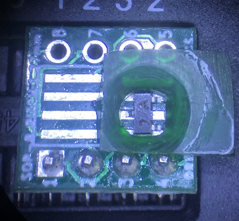
The first few attempts to test a component were a complete failure. I used tweezers to apply pressure to the chip, but the readings were either 'No component found" or sometimes a single diode (between pins 1 and 2).  I tried cleaning the contacts with Isopropyl alcohol and lightly burnishing the contacts, no help.  Seeing how I used super glue to attach the adapter, decided to try some acetone.  This worked much better and soon I was able to reliably test the component.  It appears that the super glue seeped under the plexiglass adapter and on the contacts, creating a insulator on top of the contacts.

The opening is just a bit to large, allowing the component to flow about a bit, but at least I am able to easily load and unload the component with tweezers.  I might have another go at it, but for now I think that a concept has been proven.  In the future, I might want to try a hybrid approach using a 3D printed holder and lid, but a machined plexiglass insert (with a slightly better fit).

Thanks for reading along!

  • Sign in to reply
  • DAB
    DAB over 2 years ago

    Interesting post.

    • Cancel
    • Vote Up 0 Vote Down
    • Sign in to reply
    • More
    • Cancel
  • genebren
    genebren over 2 years ago in reply to dougw

    That is an interesting thought.  I will have to look into trying something like that.  I have had some concerns that there are some size variations in some packages.  I would not what to make the fit too tight, but it might be possible to get a bit more positioning help from a tab here and there.  Thanks for the good idea!

    • Cancel
    • Vote Up 0 Vote Down
    • Sign in to reply
    • More
    • Cancel
  • dougw
    dougw over 2 years ago

    Looking godd.

    Maybe you could spray the apparatus and a component with mold release or oil, fill it with hot glue and make a positioning frame for the part. 

    • Cancel
    • Vote Up 0 Vote Down
    • Sign in to reply
    • More
    • Cancel
element14 Community

element14 is the first online community specifically for engineers. Connect with your peers and get expert answers to your questions.

  • Members
  • Learn
  • Technologies
  • Challenges & Projects
  • Products
  • Store
  • About Us
  • Feedback & Support
  • FAQs
  • Terms of Use
  • Privacy Policy
  • Legal and Copyright Notices
  • Sitemap
  • Cookies

An Avnet Company © 2025 Premier Farnell Limited. All Rights Reserved.

Premier Farnell Ltd, registered in England and Wales (no 00876412), registered office: Farnell House, Forge Lane, Leeds LS12 2NE.

ICP 备案号 10220084.

Follow element14

  • X
  • Facebook
  • linkedin
  • YouTube