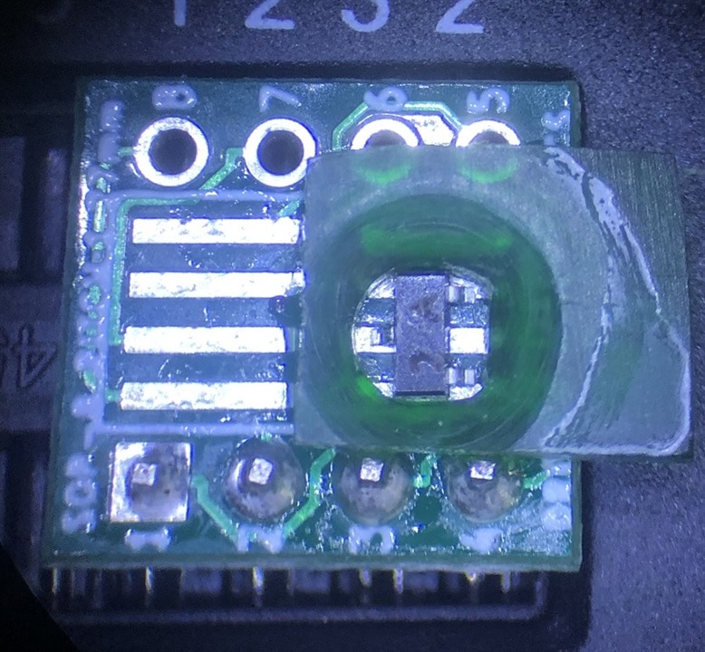
In my prior blog ( TC2-DSO review - SMT test adapters ), I used my 3D printer to create some SOT23 and 0603 component adapters. While the printed parts worked, they were by no means perfect (not close to enough resolution with my nozzle on my 3D printer) . They also required a 3D printer in order to build and as we all know, not everyone has a 3D printer. In the comments to the prior blog, shabaz presented some ideas on how to un-3D-printer up a solution to building some component adapters. This comment and the ensuing reply stuck in my head and became the starting point of this blog.
I attempted to solder wires to the test adapters that I used on the prior adapters (similar to my suggestion to shabaz), but it was really tough to keep things in alignment and to keep solder from flowing into pads where the SMT components were supposed land. So, I did a pivot. I thought that I might be able to simply machine some plexiglass component outlines that I could glue onto the test adapters. I started with the Eagle 'package' I have been using for the SOT-23 models. Centered on the component, I looked for a circle that meet flush to the edges of the device.

This worked out to be a 1/8" hole. I noticed that the circle was not quite large enough for the two lower leads, so I decided to try and flatten the bottom part of the circle.

I then found a small scrap of plexiglass (0.095" thick), which I drilled a 1/8" hole. I then used a small file and scalpel to flatten out the bottom of the hole. Test fitting the component inside of the hole I relatively happy, but I did notice that the top of the component was far from flush with the top of the plexiglass. I then used a 1/2" drill bit to ream out the top side of the hole (by hand). Later, I trimmed down the plexiglass to be a closer fit the PCB test adapter (including a bevel on the lower edge to clearance the pins soldered to the PCB) and glued it onto the PCB test adapter.


The first few attempts to test a component were a complete failure. I used tweezers to apply pressure to the chip, but the readings were either 'No component found" or sometimes a single diode (between pins 1 and 2). I tried cleaning the contacts with Isopropyl alcohol and lightly burnishing the contacts, no help. Seeing how I used super glue to attach the adapter, decided to try some acetone. This worked much better and soon I was able to reliably test the component. It appears that the super glue seeped under the plexiglass adapter and on the contacts, creating a insulator on top of the contacts.
The opening is just a bit to large, allowing the component to flow about a bit, but at least I am able to easily load and unload the component with tweezers. I might have another go at it, but for now I think that a concept has been proven. In the future, I might want to try a hybrid approach using a 3D printed holder and lid, but a machined plexiglass insert (with a slightly better fit).
Thanks for reading along!

-

dougw
-
Cancel
-
Vote Up
0
Vote Down
-
-
Sign in to reply
-
More
-
Cancel
-

genebren
in reply to dougw
-
Cancel
-
Vote Up
0
Vote Down
-
-
Sign in to reply
-
More
-
Cancel
Comment-

genebren
in reply to dougw
-
Cancel
-
Vote Up
0
Vote Down
-
-
Sign in to reply
-
More
-
Cancel
Children