You may recall from Part 2, I became the proud owner of a Multicomp Pro MP710259 DC Electronic Load, which also sells under the Tenma 72-13210 designation in some markets and is a Korad KEL103 rebadge. It surprised me with its relatively accurate metering and genuine power rating, especially when one considers the price of the equipment.
But now, I’m bringing you a post about a teardown, repair and test. So, did I break it already? Thankfully no … instead, I’m blogging about the first unit that was shipped to me that was presumably damaged in transit somehow. When I extracted it from the box, it made a loud “thunk” when it was tilted as if there was something loose inside. That was not what I expected and I wasn’t going to risk powering it up in case it harmed something, so I contacted srutledge and rscasny about it and they were nice enough to organise a second unit to be sent (which was the one reviewed in Part 2).
After recently contacting element14 about what to do with the first unit, after some checks, it was decided that the unit will be written off as they were not definitive about how the damage came about as it had been shipped multiple times, but also because the cost of return shipping would be quite expensive (Australia is half-way across the world). Another consideration was that this was their “own brand” product, so it would not be a major issue to let me “dispose” of the unit in any way I saw fit.
Let’s just say, I’m not a fan of unnecessary e-waste, and I did offer to venture a repair on the unit at first, although I wouldn’t know the full extent of the damage until disassembly and that may destroy evidence necessary for an insurance claim (if that was how they were to proceed). Now that I have the green light to take possession of the unit, I decided it would be the unit to be opened for a full teardown in the name of a repair attempt with the experience documented for the community. That’s the least I could do! Of course, with any precision equipment, any “lid-off” time is a risk to calibration and accuracy … so this will be the sacrifice.
What’s the Fault?
So, it clunks … what might the problem be? I thought it was loose and heavy, so it was probably a transformer, but it also seemed to be at the front of the unit. Most products I know generally have the transformer somewhere near the power inlet which would be on the rear … so this was a little confusing.
The only way to solve this was to pop open the unit. This was achieved by removing four screws in the back and another four on the underside which allowed a rear plastic surround and the metal shell to be removed.
Et voila! Well, that’s a surprise. The transformer is in the front indeed and the mains seems to be handled by a thin wedge at the top side of the PCB. The main body of the unit is dominated by a tunnel/channel heatsink with the fan blowing from inside. We’ll look a little more closely at the PCB in the next section, but it was a relief to see that it wasn’t completely trashed … I was afraid it would be a “bull in a china shop” situation.
After some prodding, it turns out I am right. This transformer was rocking back and forth with mounting screws that seem to have backed out partially but not enough to let go. But the rocking has also bent the mounting arms … and the design of this unit is awkward in such a way that it is impossible to screw the transformer down with the main PCB in the way! A full teardown is mandated if one is to repair this.
I guess one could stop here if they were satisfied that they weren’t going to be rocking the unit and/or the transformer and its shielding were not going to touch anything, but I could see that any rocking was going to make the mounting arms scratch against the underside of the PCB, so I really didn’t want to leave it at that.
Peering Closer at the Internals
Let’s take a tour of the insides as I commence my reconnaissance (as there's no service manual as far as I can tell) and decide how to take it all apart. First on the list is the front panel.
The front panel is made of a PCB (KD-LOAD ELED V1.5 dated 20190824) which connects to the main PCB by a ribbon cable terminated in 2.54mm 16-way two-row sockets. The beeper is visible on the rear. The whole front panel assembly can be removed by removing the four screws around the side and the two screws that connect the main busbars from the main PCB to the binding posts on the front.
Looking at the top left, we can see the mains power part and isolation clearly marked in silkscreen. The reason the power comes all the way up front is simply because of the mechanical power switch. Looking closely at the board, it seems it is quite shiny – it seems there is a thin layer of conformal coating which should help the circuit resist environmental effects from dust or humidity. Also apparent is a number of TO-220 packages, some with their own small heatsink.
The fan is mounted on the inside of the unit and is configured to blow through the channel and exhaust out of the rear of the unit. Such a positioning is not ideal for easy cleaning.
Along one side of the channel is the communications interfaces which seems to be handled by a separate microcontroller. The terminal block for sense and trigger is connected to a header on the mainboard. Aside from that, there seem to be mainly small parts (e.g. passives, opamps) which are hard to identify as the conformal seems to have filled in their part numbers.
Along one side of the channel, we can see four beefy MOSFET packages each with a feedback balancing resistor clamped to the heatsink. More on these later in this section.
The other side of the channel has the mains input filter arrangement and the RS-232 level shifter and connector underneath.
The arrangement of semiconductors is practically the same on this side, with the exemption of a temperature sensor on the heatsink.
From what I can see, it seems an STM32F runs the show, with a Winbond EEPROM for data storage.
The input stage above has a number of beefy MOVs to handle surges or overvoltages (with a nasty bit of solder splash on R1 which I cleaned up), and a few capacitors as well. There seems to be some R-C combination here as a filter. There is a Nexem signal relay (K1) which is probably in charge of the remote sense path switching. The main PCB is marked 101-02-000-037 V5.2 dated 20230222 making this a very late model by the sounds of it.
A closer look at the communications chips – it’s no surprise Ethernet is being handled by a Wiznet W5500, quite similar to how it is handled on an Arduino Ethernet Shield. The USB connection would seemingly be handled by the chip marked KORAD5.1 dated 20220906. I suspect, based on the USB VID, that this maybe some Nuvoton ARM SoC.
A closer examination of some of the signal processing and power components nearby. There seems to be a whole spot that is left unpopulated – I wonder if that is for a larger power-rating model or something else entirely.
One thing I did not expect to see is that the unit appears to use a classical R-2R DAC arrangement. Just look at that array of 01C (10kΩ 1%) and 30C (20kΩ 1%) resistors! Brings back memories of undergraduate university electronics lab exercises.
Back to taking it apart … say goodbye to the front panel module … wait …
… say hello to the inside of the front-panel module. This is a rather curious finding – that LED module display seems to have been soldered down by someone who didn’t understand that the modules usually are “raised” off the PCB by legs at the corners and the leads should be arranged such as to keep the module flush. In this case, it seems someone was hell-bent on pushing the module legs through the board and soldering it down that the whole module is bent. Luckily, there is no damage, although it seems the protective film was not removed either, leaving a glossy finish.
The front keypad, as many are, is made of a rubber membrane pushing conductive spots on gold-plated interdigitated traces to close a circuit. It seems this board is predominantly filled with shift registers – nothing too smart.
The rear plate can be removed with a few screws. Luckily all the fixed sockets are connected with connectors that can be separated. The white silicone material they use to secure the connectors is very flaky and comes apart at the lightest touch. The screws on the DB-9 connector shell, thankfully, do not secure against this rear plate, making removal very easy.
Now with the ability to get closer by removing the board from the chassis by removing some nylon screws from the underside, we can examine some of the components more closely. It seems these capacitors come from rather unknown manufacturers – Jwco and KSC. Perhaps this is okay if the circuit is not subjecting it to high ripple currents.
The temperature just seems to be a thermistor. Perhaps they had a TO-220 or a ring thermistor at one stage, but adapting an SMD thermistor with a small PCB might have been cheaper or easier for them.
More random capacitors, transistors and a venerable ST L7912CV linear voltage regulator (actually, a few).
Some are hiding in the heatsinks!
The RS-232 level shifter can be seen here – a Sipex SP232EEN, which is a clone of the venerable MAX232.
For curiosity, I disassembled the restraining clips on the resistors on both sides and got a good shot of all the power semiconductors.
I used the excess thermal paste to make the markings on the semiconductors more visible in the shot. They are all Maspower MS50N20FC 200V 50A 0.04Ω N-channel MOSFETs in a TO-247 package. It seems that having eight packages is quite a nice touch as it spreads the rated 300W dissipation down to 37.5W per package. These all look identical which is nice.
These are all next to BPR56 0.05Ω non-inductive resistors. At first, I thought they were wire-wounds, but that wouldn’t make sense as transient operation would be problematic. These appear to be feedback balancing resistors to ensure currents are shared roughly equally between all of the MOSFETs. However, the marking of “KUA5N5” is a bit curious, as I think this might be a bit of a copy of the KOA Speer products which are often marked with KOAnnn as well. The fact they are printed in different directions on the devices doesn’t fill me with confidence that these are high-quality, but then again, as they are simple parts, perhaps they don’t need to be anything special.
The fan is a Runda RS7025B12VH-A, 12V DC 0.27A rated brushless 70mm x 25mm computer style fan. The size is not quite common, but we can take solace in the fact the fan claims itself to be “good quality DC fan”. I’ll take your word on that.
While I removed it from the frame by bending over a few components and wedging in my screwdriver, this does not appear to be the recommended way. Removal of the whole frame by taking out two screws from the underside of the PCB seems safer.
We can see that the two thick copper-coloured wires bent into a wavy shape are likely a big current shunt, with the board capable of accepting up to four of them. Perhaps a secret to its current accuracy is the fact the shunt is actively cooled by the fan, and the temperature is somewhat regulated by the heatsink temperature and thermostatic control of the fan, so reading drift due to shunt heating is minimised.
The underside of the PCB looks like this … if only they had just designed the PCB cut-out just a bit wider so that we could get to the transformer screws without having to remove the whole board, all of this may not have been necessary. There seems to be quite a lot of tinning and even some additional metal soldered down to allow the PCB to handle the 30A current.
There is an insulating plastic sheet in the base, which leaves us with the transformer that needs to be removed, bent into shape and reinstalled.
The loose screws and bent mounting ears are clearly seen there. By now, I’ve got the load stripped down to the bones … time to put it all back together again!
Post-Repair Test Results
As I don’t want any surprises for anyone who might stumble across the unit in the future, I decided to label the main PCB internally to make it unambiguous that I have been inside.
I also put a label on the outside of the unit on the top. Powering it up, it’s definitely alive.
I did a full load test on it and it managed to sink the 300W with no sweat!
The thermal results look very similar to before.
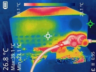
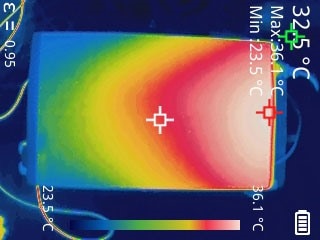
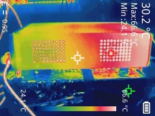
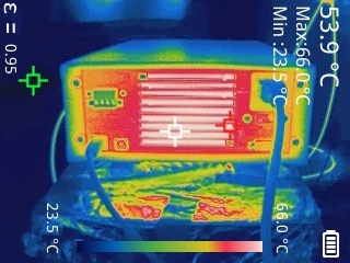
So far, so good, but did the calibration survive the torture?
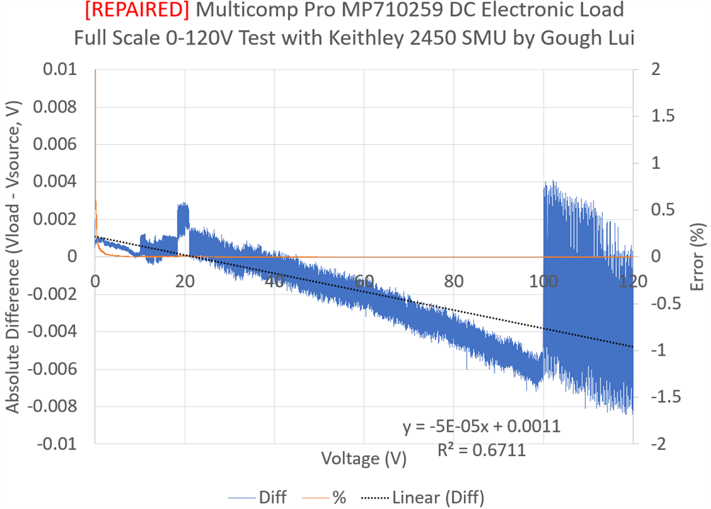
Checking voltage accuracy against my Keithley 2450 SourceMeter SMU across the full range, the disagreement reached a little more than 8mV at the worst and overall, below about 60V, it stays within 3mV. That’s not a bad result at all.
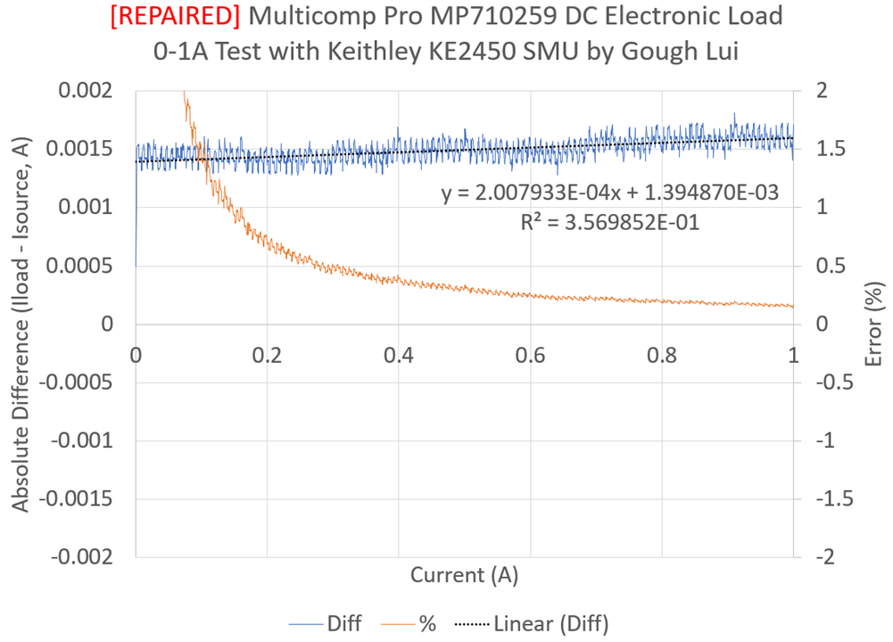
Checking current accuracy at low currents against the SMU showed it was pretty much dead-on accurate except for an offset of around 1.5mA. This would suggest the calibration survived.
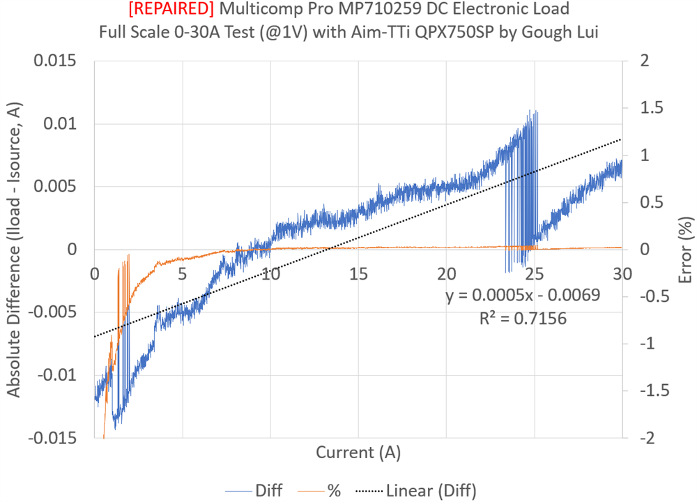
Testing across the full 30A current with the Aim-TTi QPX750SP Power Supply, the errors were within 15mA which is acceptable given the QPX750SP reads out in 10mA granularity.
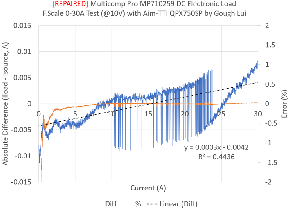
For an additional challenge, I forced the load to drop 10V so that it would test sweeping up to the full 300W and the results were no worse.
Based on this, I can only consider the repair operation a success, as these results are quite similar to the fresh, unopened unit.
Testing Transient Mode
Now that I have a unit on the bench that works, why not devote some time to master the use of the transient mode from the front panel? The LED segment display doesn’t make this easy, but we have the help of our trusty manual!
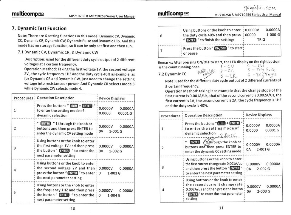
Actually, it seems the manual does have a small mistake and is somewhat incomplete, so I’ve annotated this page with the actual mode numbers and the fact that CC is “2” and not “1” which is why I couldn’t get dynamic CC working in the first place. Now that this confusion is resolved, I can now run some waves under the watchful eye of the Rohde & Schwarz MXO4 oscilloscope (review pending) and with the Keysight E36103A Power Supply providing current.
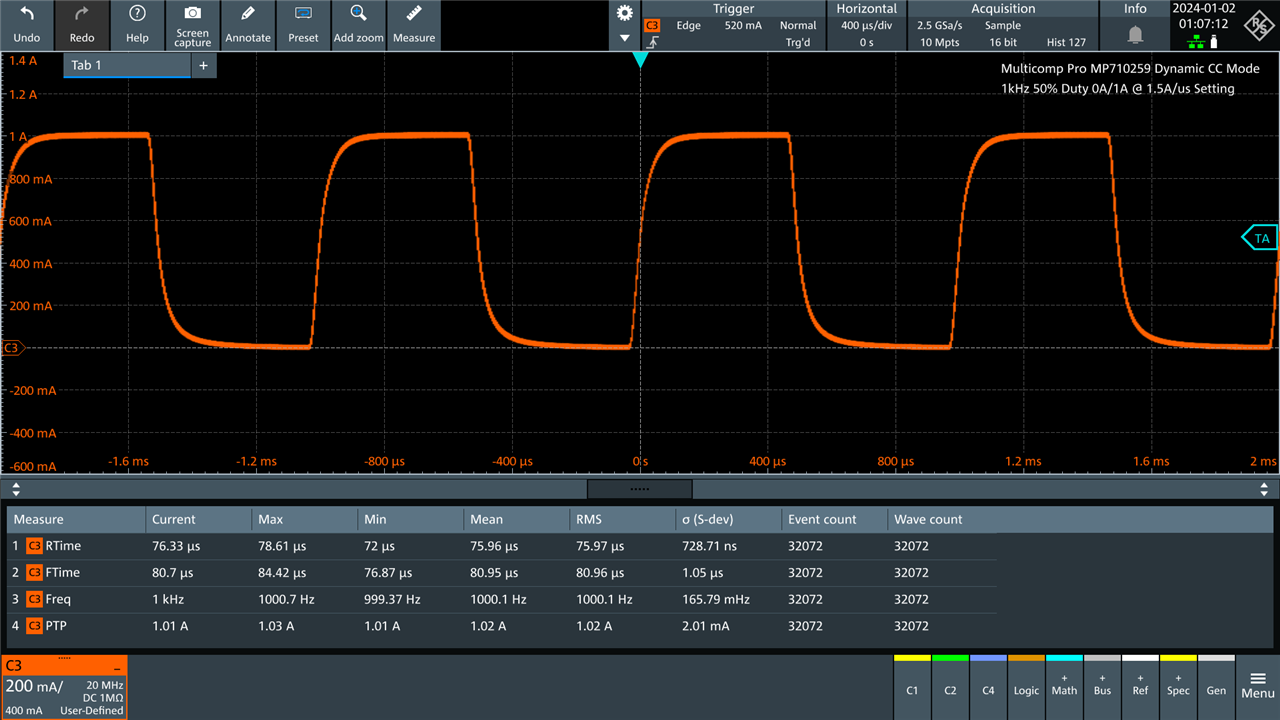
I used a resistor to measure current flow and a custom probe configuration so that the oscilloscope can readout directly in amps. In this case, 0A-1A transients at 1kHz at 1.5A/us slew rate shows that the load isn’t entirely under control, with some “curvature” of the slopes.
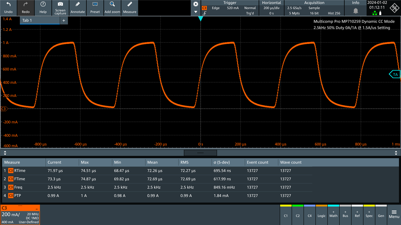
At 2.5kHz, I’m seeing something that resembles more of a shark-fin.
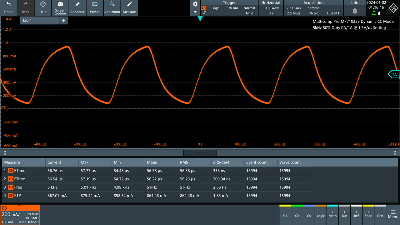
At 5kHz, it’s definitely not a square wave anymore …
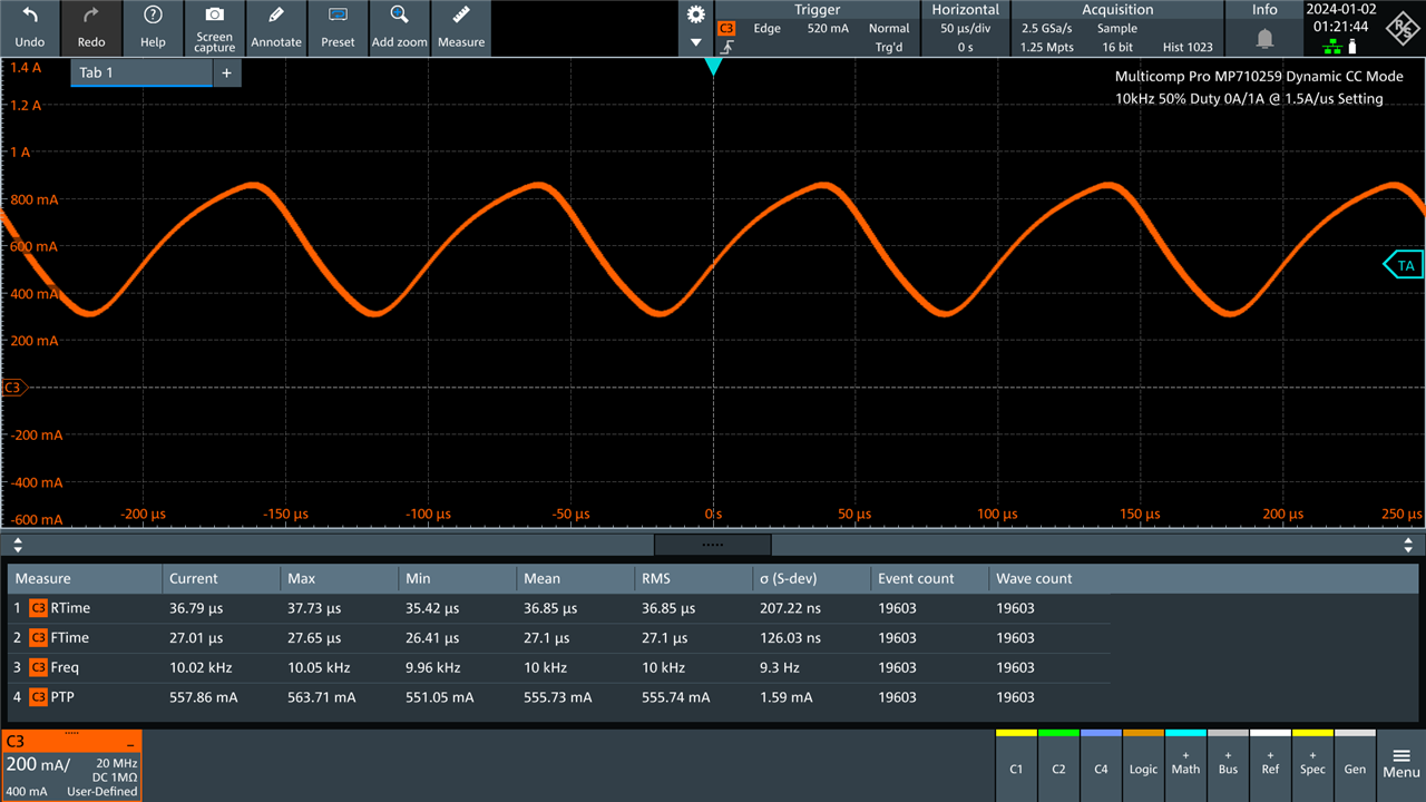
At 10kHz, it can’t keep up even with 0-1A thus it results in this sawtooth instead. It’s not quite symmetrical either, suggesting that increasing load is slower than decreasing load. As a result, while the advertising brochure may say 10kHz, it will depend on what sort of current values you’re using.
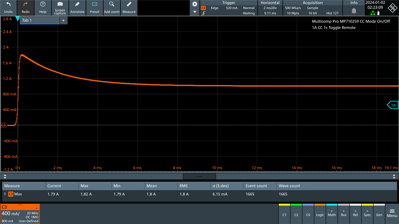
One unexpected shortcoming was that turning the load on or off results in an overshoot. In this case, selecting 1A and toggling the output on and off via remote SCPI repeatedly resulted in this stacked plot showing that the peak current reached an average of 1.8A, 80% higher than programmed, before settling towards the expected value by about 8ms. This is still “fast” by some standards, but is a notable result.
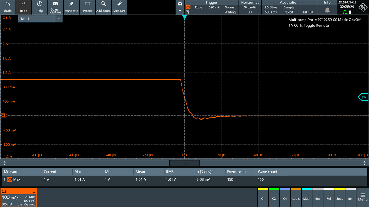
Turning the output off doesn’t result in much undershoot, as expected, as the load itself cannot “source”. Some of the observed behaviour may be due to the Keysight power supply’s regulation loop interacting with the load, however.
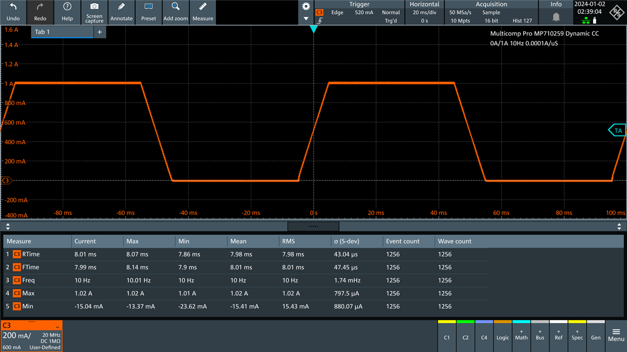
Choosing more gentle and slow settings, such as 10Hz and 0.0001A/us slew rate, the output is much better controlled. As a result, it’s probably quite suitable for running pulsed tests on batteries (as long as the pulses are not too short, but perhaps not quite fast and clean enough to stress out high-end lab power supplies (which I still find the B&K Precision Model 8600 to do well on, especially with its Imonitor output).
Finishing Touches
Before finishing up, I decided to treat both of my loads to the proper (well, I thought they were) fuses.
The packet of fuses finally arrived for me.
These are 0.5A fast-blow rated M205 fuses, which I thought were the right ones as the originally supplied fuse was a fast-blow fuse. Looking through the manual, it seems that time-delay (slow-blow) fuses are the correct type according to that. Nevertheless, if it doesn’t cause nuisance blowing, then there should be no problems as the fast-blow fuses are more conservative (safer) than the slow-blow fuses.
It was during this replacement that I found there was a second spare fuse located in the “boxy” hollow section of the fuse holder. This isn’t used for the “second leg” as it might be in some dual-pole fuse holders, but instead, was a spare fuse from the factory. A nice touch indeed. But unfortunately, also not the right value for 230V usage. I prefer to be safe than to be sorry, but I suppose the original fuse is still relatively low-rated, so there isn’t likely to be any major damage in case of a fault even if the fuse value was not changed with a change of voltage.
Another thing to mention was the quirky MAC addresses. Turns out this unit has an odd one too, but it was not the same as the other unit, so both can nicely co-exist on my network. The last three octets of the MAC were also 00:00:00 which is very unusual – it suggests that they’re probably customising these strangely at the factory or have the endian/byte order wrong as they’re changing the OUI for each unit.
Conclusion
The fault was as I had originally anticipated – simply a transformer that somehow became loose possibly in transit due to vibration or rough handling, rocking forwards and backwards and bending its mounting arm. The fix required a full teardown, which gave us a good appreciation of its internals which seem decent overall. The bent arms were straightened and the transformer reinstalled with superglue as a substitute for thread-locker, the remainder of the unit was reinstalled and it seems to have passed all tests with flying colours. Back in service, and perhaps as good as new!
I also gave the transient mode a quick test too – programming using the front panel is a bit tricky without the manual, but I spotted a small mistake even with the manual. Nevertheless, I also made the finishing touches to the repair by swapping out the fuse with a more conservative fuse for 230V operation (although fast-blow, rather than time-delay, as I had some confusion – the manual states time-delay for all fuses, but the provided fuse was a fast-blow fuse). So far, so good, the unit seems to operate just fine and it turns out it does have a unique MAC address too, but one with many zeroes in it suggesting some strange practices in terms of device personalisation.
As a result, this unit is not a waste after all … and now I’ve ended up with two working units. I can’t complain … but now I feel a bit silly for complaining about the clunk in the first place.
Epilogue
You may have heard from the grapevine that I will be taking a hiatus this first half-year from many things, including element14, in part because I have not taken any leave from work in way too long and in order to spend quality time with family. As part of my preparations for this time off, I have been dutifully clearing off my “to-do” list so that I can hopefully leave my post in early March with a clear head. In delivering this blog post, I have fulfilled all of my planned major commitments to element14 at this time and as such, you can expect to see or hear much less from me (except for an occasional comment or two) until I return sometime in the latter half of 2024.
Thanks for your support of my content and I wish you all good luck with your endeavours this new year.


Top Comments