


In the spirit of Christmas and of being thankful, this second half of the grand prize was, in itself, also not free of logistical difficulties. Thanks to rscasny and srutledge , a Christmas miracle happened, which is why I’m posting this today. It is a rule that when test equipment turns up ... it gets tested!
A False Start
The first unit arrived on the 1st December, but unfortunately, it seems it was handled roughly during shipment. When unboxing the unit, I found it had a loud “clunking” whenever the unit was moved, indicating something inside was loose and moving about. I wasn’t confident to plug it in and test it in this state, as it could seriously damage the equipment.
I let Randall and Sean know about this immediately via e-mail to see if there was anything that could be done. Perhaps there could be an insurance claim against the shipper which would require preserving the evidence, or perhaps there could be an option for repair, replacement or exchange. I know that they didn’t have to help me – it wasn’t their fault it was damaged, so I sent off the e-mail also explaining that if there wasn’t anything that could be done, that would be fine as well.
Rather generously, element14 organised a replacement unit to be sent as soon as possible. Based on their dispatch date, they were expecting arrival on 28th December … but by some miracle, it arrived on the 22nd, making it in time for Christmas.
Unboxing, Feature Introduction and Setup
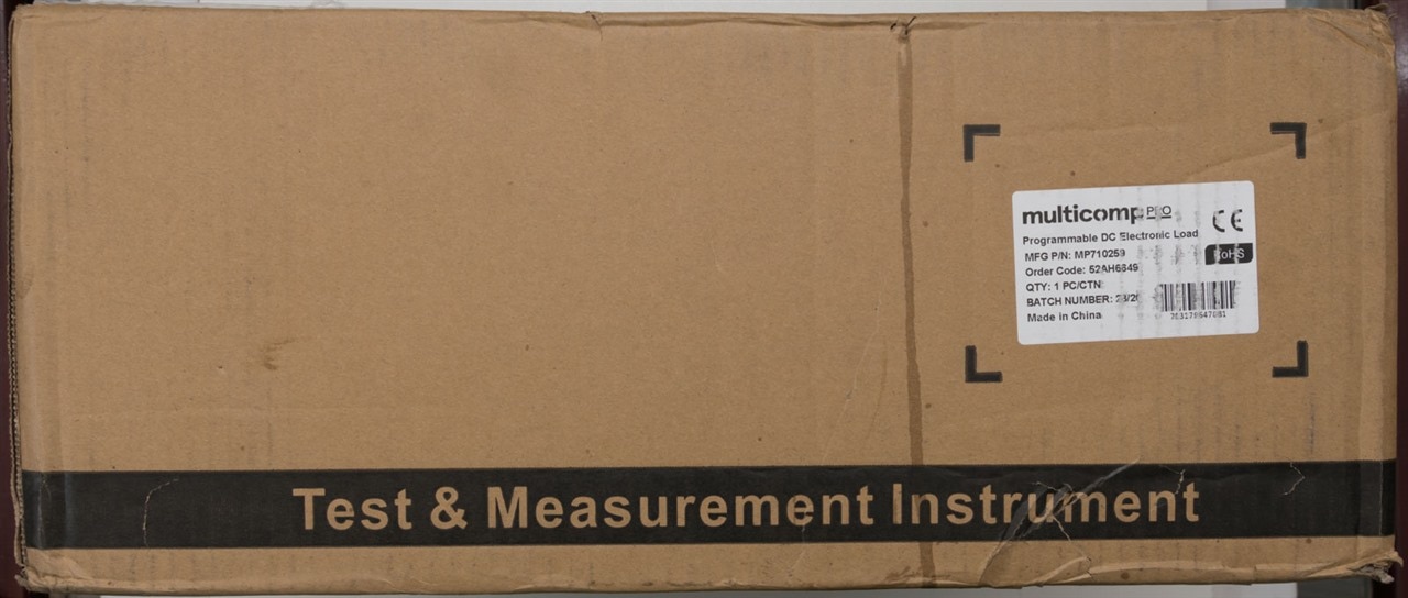
The unit arrived, shipped in its original box. This is the second unit and externally, some signs of rough handling are present too – some of the packing tape had “busted” apart and there were signs of crushing in some places.

Internally, the unit is suspended from all sides and accessories are placed into this void. There is sufficient clearance and foam ends to protect the unit, so one would expect it to survive.
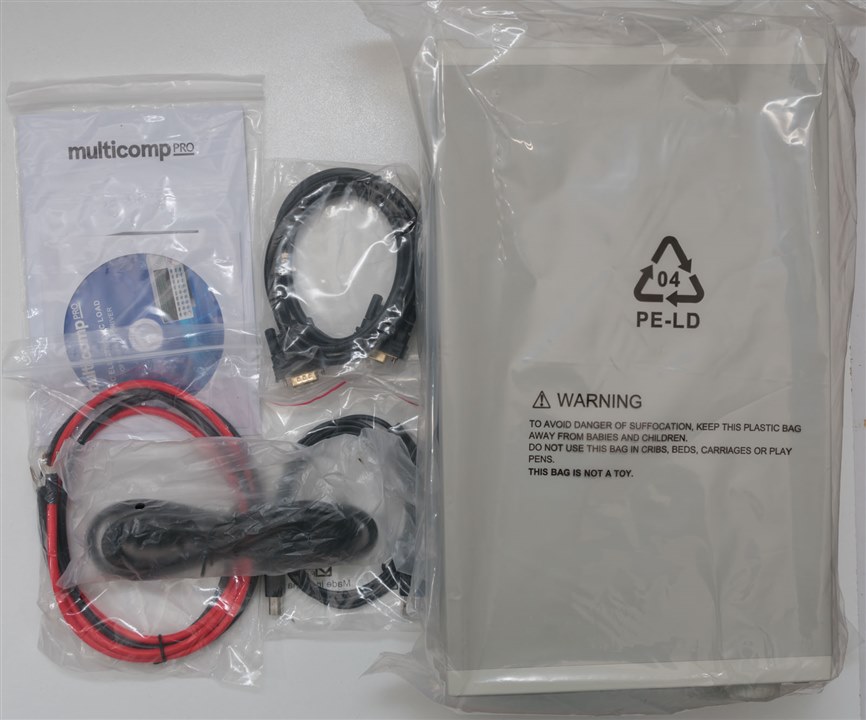
The set comprises of the unit, a US power lead, a DB-9 straight-through serial cable, a USB A-B cable, a set of 10AWG silicone wire terminated in spade lugs and a bag containing a user manual and CD-ROM.

If you think it looks familiar, well you’d be right. This is almost certainly a rebadged Korad KEL103, a unit which is quite popular with hobbyists due to its reasonable price and good specifications. As the RoadTester of a B&K Precision Model 8600 DC Electronic Load from 2016, it is rather interesting to think that the Multicomp Pro MP710259 lists for USD363.98, while the current B&K Precision Model 8600B lists for USD1,290.00. You could almost get four of the Multicomp Pro units for the same price as the B&K, but also, the Multicomp Pro unit is rated at 300W rather than 150W of the B&K. If you think accuracy is the differentiator – in CC mode, both claim 0.05% +/- 0.05% FS, so things aren’t as different as one might assume. While there are differences in user interface (matrix VFD vs segment LED), remote interfaces (GPIB vs LAN), and transient generation (10kHz vs 25kHz), the Multicomp Pro does offer undeniable appeal when price is considered.
The front itself has two screw-down post terminals for the cable connection, a window for green 7-segment LED displays and a three-row keyboard with a mixture of translucent and solid colour rubber keypad buttons. A rotary encoder knob and up-down keys are also provided, but the knob has no centre-click. It would seem most buttons have two features, the “shift” feature is indicated in blue print on the case. This is a fairly old-school user interface and one that is not entirely user friendly.
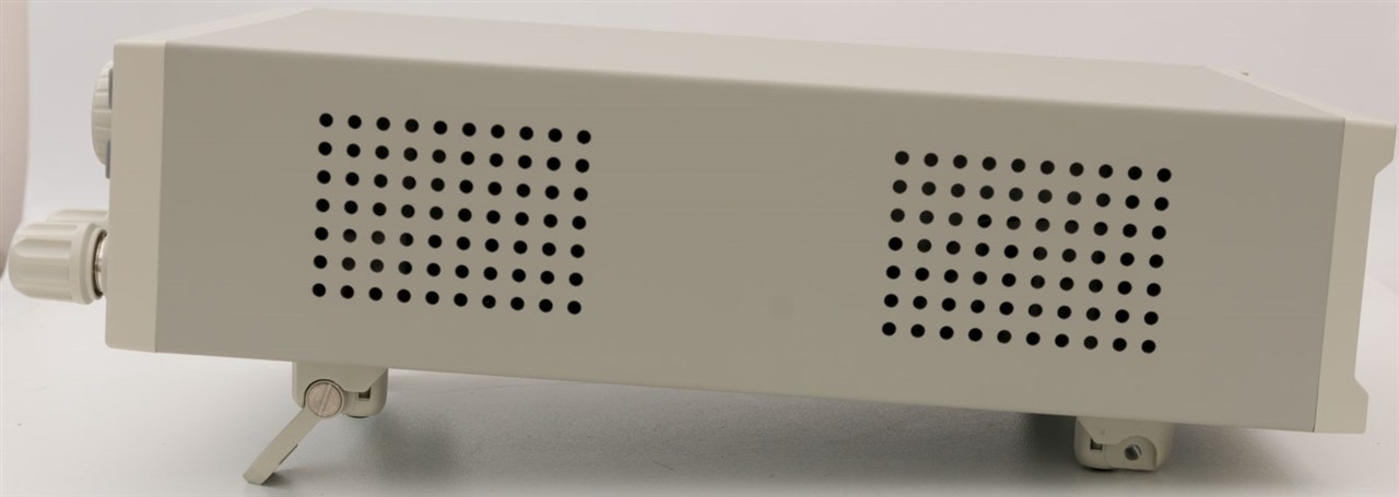
The unit features flip-out front feet for elevating the unit at an angle if desired, which can be retracted so that the unit sits flat. There are vent-holes on one side for cooling, while the top surface is solid.
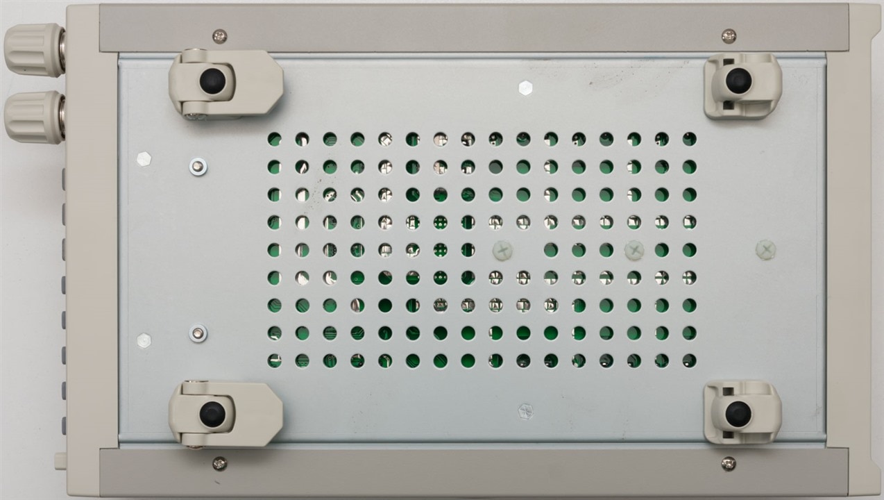
The underside has rubberised feet for a more stable footing on the bench, with some vent holes exposing the underside of the internal PCB.
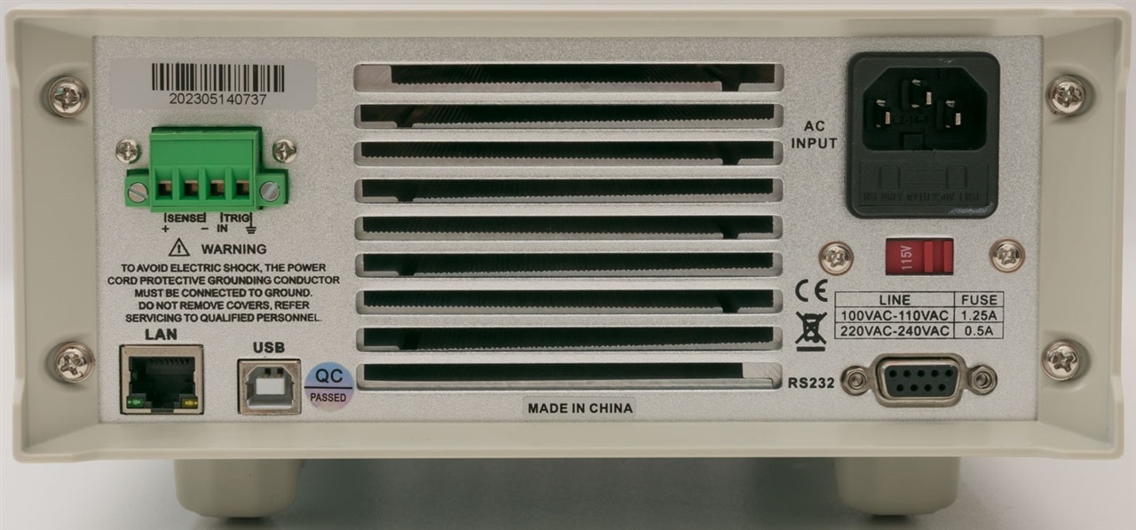
The rear of the unit is dominated by an exhaust vent with an aluminium channel heatsink visible. Power comes in through a fused IEC socket. Computer interfaces include RS-232, USB and Ethernet LAN. A pluggable terminal block offers remote sensing (four-wire Kelvin) connection and trigger input.
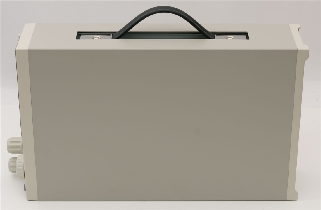
Rather interestingly, the handle on the other side allows for the unit to be carried around, a bit like a briefcase. This would be a nice feature, if it were not for the fact that the hardware is sunken into the case, surrounded by a rather sharp metal lip which could be a bit of a cut hazard.
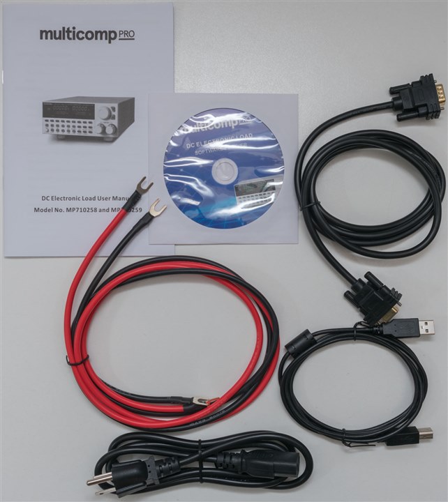
The included accessories are rather generous, considering the price.

One really has everything needed to get started – 10AWG silicone wire is well rated to handle 30A (if not, a little more).
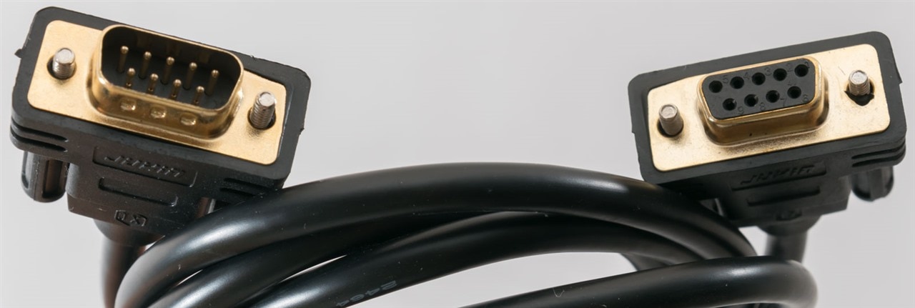
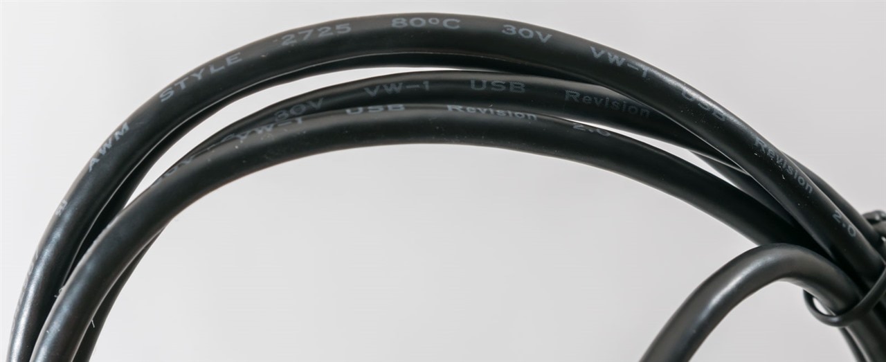
The DB-9 to DB-9 serial cable is especially handy when using with older computers or controllers, or a dedicated USB-Serial port. The USB connectivity is appreciated for more modern computers, while LAN eases integration into larger test set-ups. The provided USB cable seems a bit thin, but is appropriately typed. There is no GPIB option or capability, which is one downside, but one that is easy to live with given the age of the interface.

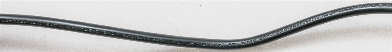
A US power cable from Hong Shan Chuan is included (18AWG), which I substituted for a local IEC power cable instead.
Living in a 230V country, running this load is not as simple as sliding the switch on the rear to say “230V”.
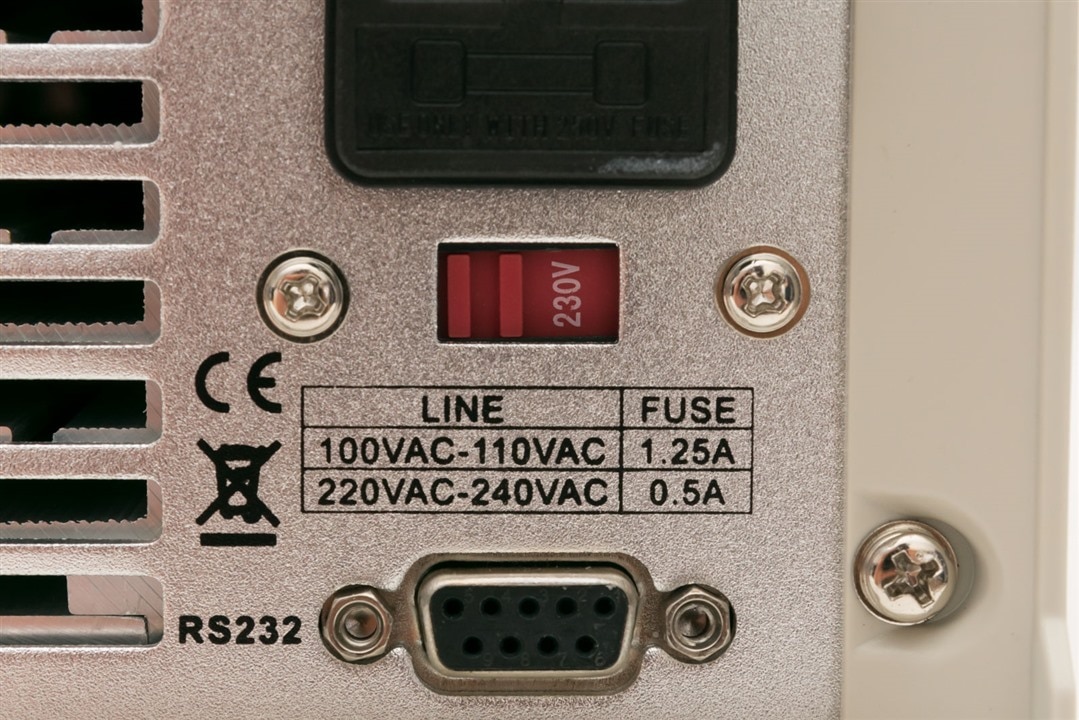
If you look closely, the fuse rating for 220-240V is 0.5A. The fuse provided is a 1.25A for the US market. The blowing characteristic is not specified on the device, but the manual says it should be a “T” type, for time-delay or “slow-blow”. Curiously, the installed fuse is an “F” type, for “fast-blow”, so the provided fuse isn’t the specified fuse either (but is more conservative).
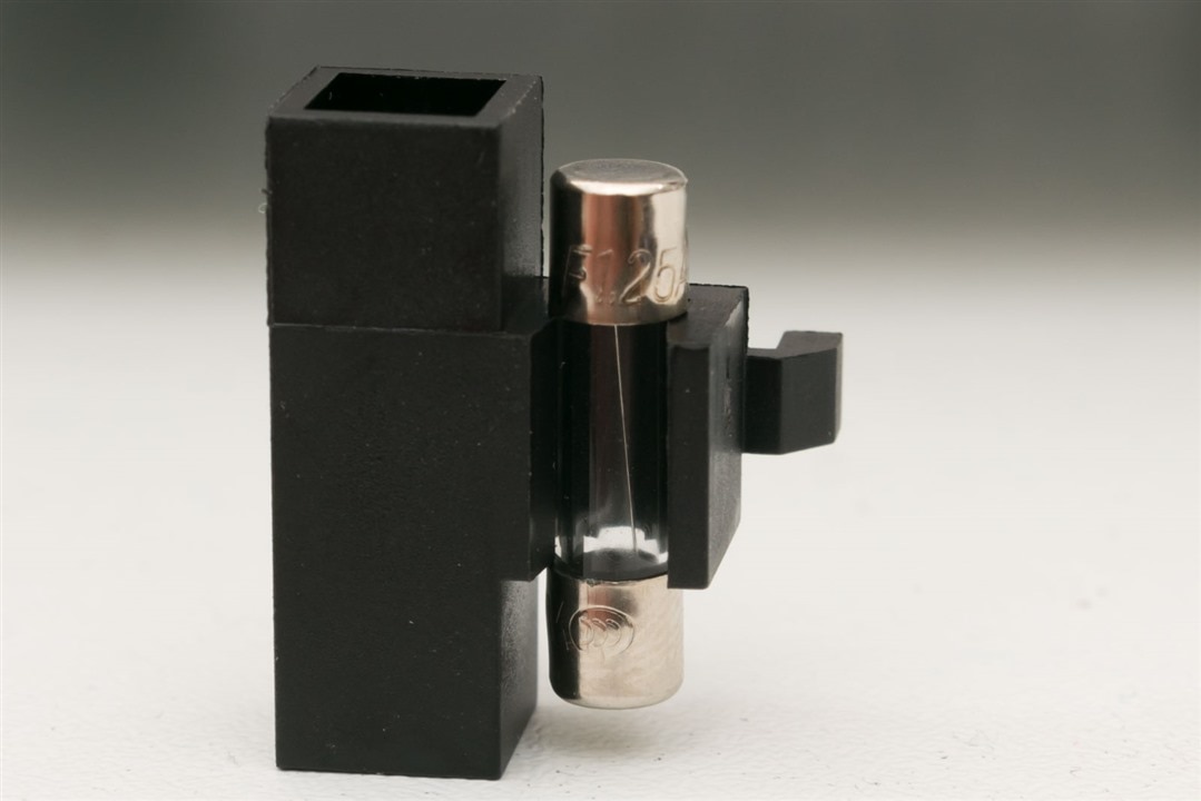
As a result, for safety, it should be changed to a 0.5A fuse to ensure an appropriate level of protection is provided to the equipment in case a fault occurs. I ended up rushing out to a local shop to grab some fast-blow 0.5A M205 fuses to replace it just to be safe. If you don’t (at your own risk), nothing bad is likely to happen if the equipment is working fine. Even if it fails, perhaps a limited amount of extra damage would occur with the wrong fuse, but a catastrophe seems rather unlikely.
Aside from that, one simply pushes the hardware power switch … and it’s ready for use on the bench!
User Interface and Documentation
The user interface for the DC electronic load is clunky at best. The use of fixed-indicator LEDs and 7-segment displays produces an interface which is fast (with about 5Hz reading refresh rate) and sharp for reading out programmed values and measurements, but nearly impossible to use intuitively when it comes to configuring more advanced capabilities. Only a very limited amount of text can be generated with the display, leading to non-sensical displays and input entry sequences for certain features that make it difficult to use without reference to the manual. With keys that perform different functions depending on the “shift” key, the potential for mis-keying is increased. The keys are also small and closely spaced together making it easy to inadvertently activate the wrong function. The light-up translucent mode function keys are useful to tell what is happening at a glance. I suppose this is the key difference between the B&K Precision Model 8600 – that uses a dot-matrix VFD which is capable of providing textual menus which makes for easier configuration despite sharing the same “shift-key” multi-function button user interface.
Unfortunately, it seems documentation is a bit of a mess. There is a supplied user manual booklet within the pack which is very important to help figure out some of the cryptic front-panel user interface, but it is written in a very terse fashion with copious spelling errors, missing information and unclear indications of what to expect on the user interface. It is difficult to follow without expending some effort in trying a few different combinations of options in order to decipher what the manual writer intended to convey. Unfortunately, this manual is not included on the CD-ROM but can be downloaded from the product page.
As for the CD-ROM, I would hazard to guess that many users may not have the equipment to read them anymore. Regardless, it contains a driver, test software and configuration software along with installation instructions for the driver and information about IP programming and the remote-control command-set which is vital for effective remote-control operation. While this is somewhat sufficient to get started with, it seems the way that these features have been implemented deviate from the standards by which branded test equipment frequently operate.
Connected Operation
This section will look at remote-control, PC-connected operation of the DC electronic load. The use of the remote-control connectivity is a known source of frustration with this particular sort of load, so let’s see if I fare any better.
I did not test serial (RS-232) connectivity as it is very basic and therefore likely to just work, but also, because the computers I am using do not have native serial connectivity. Therefore, I would be using it through a USB-Serial converter anyway … so why not just use the provided USB?
For me, the USB connectivity just worked. On both a Windows 10 computer and a Windows 11 computer, it was a plug and play experience as the port was USB-CDC compliant and installed the default drivers for a virtual COM port.
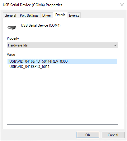
It is detected with a USB VID of 0x0416 and PID of 0x5011 which appears to be a Winbond or Nuvoton product, although I’m not sure if this is truly the case or whether they just borrowed this VID/PID pair out of convenience as it seems Nuvoton is against the use of their VID in production.
The existence of an Ethernet LAN port is an excellent feature, as it allows for integration into a larger network of test equipment and easier sharing of instruments across computers. Ordinarily, branded products would implement things by standards such as LXI, but this product does not. When plugging it in, a 100Mbit/s full-duplex Ethernet link is established, but you won’t find any DHCP request or any communications with the load at all.
The use of the CD-ROM proved especially helpful, as I could either refer to the commands for communications or I could simply use their test utility to issue the necessary commands when connected over USB to configure the Ethernet LAN interface for use.
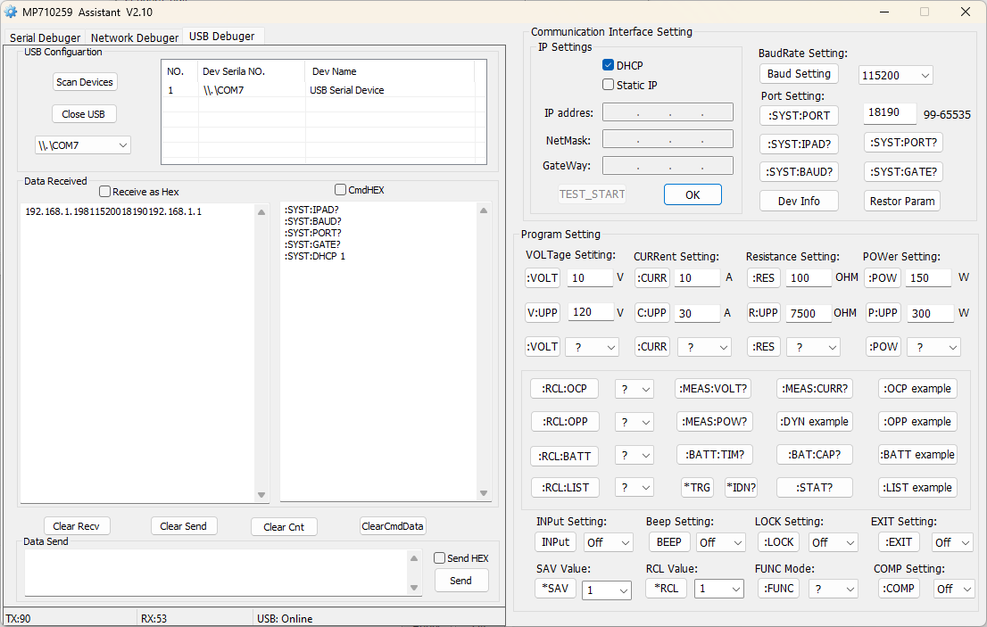
As far as I can tell, the default IP address the unit is configured to is 192.168.1.198 at port 18190. A user can enable DHCP by issuing “:SYST:DHCP 1” to the unit, however, this does not seem to behave as expected. This does enable DHCP and configures the unit to the DHCP address, but it doesn’t seem to enable a full-time DHCP client. I did not see the unit renew its lease and when switching to a different Ethernet network with a different subnet, it didn’t obtain a new lease even after power cycling. The only way to refresh it appeared to be to issue the DHCP enable command again, which is very broken behaviour. To get around this, it is safest to either configure a static address outside the DHCP lease pool, or to make a static binding for that MAC-IP pair so that no other device could potentially conflict.
The app’s discovery for the network appears to use port 18191, which is why the port of the load cannot be configured to this port number. However, as noted by the linked thread, it is broken as the broadcast address is incorrect and thus it never discovers any loads. It is easiest just to configure by USB for the first time, as a result. But even when configured, this utility cannot find the correctly configured load nor issue commands to it. As a result, one has to resort to other utilities to send commands to the load, as it operates using UDP rather than TCP.
By default, it runs on port 18190 and its protocol requires the sending computer to send on the configured port and receive responses on the same port number. I had issues getting socat/netcat to work both ways because of these requirements.
As a result, I decided to write a Python-based proxy program that would communicate with the load on a given address at port 18190, but serve it as a TCP connection on localhost port 5300 so that a traditional VISA could connect to it.
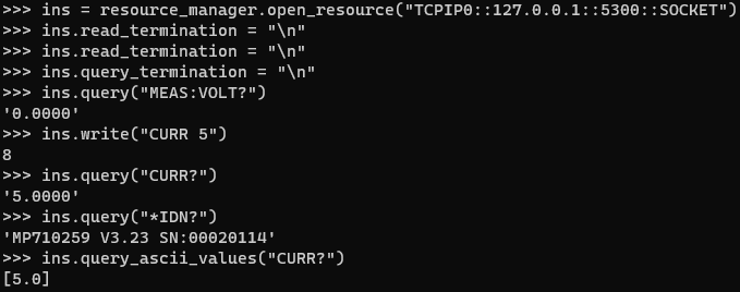
During testing, I discovered that the unit’s SCPI-like command set has a few interesting quirks – namely that all query responses will not provide just the value, but also the unit which breaks query_ascii_value calls. It is also insistent on having a leading colon on short-form commands (e.g. “:MEAS:CURR?”) but must not have them on long-form commands (e.g. “MEASURE:CURRENT?”). It is missing some common SCPI commands as well (e.g. “*OPC?”). As a result, I decided to make my proxy also do some translation work – it converts line endings, upper-cases all commands, adds leading-colons to all non-*-type commands, splits multiple commands, handles queries, translates between OUTP/OUTPUT to INP/INPUT (as this load only handles one variant) and translates function names (e.g. “CURR” -> “CC”). The program is listed below.
import socket
import time
import select

TCP_IP = "127.0.0.1" # SERVE TCP ON LOCALHOST (OR OPTIONAL BIND ADDRESS)
TCP_PORT = 5300      # TCP SERVER PORT
UDP_DST_IP = "192.168.xxx.xxx" # PUT IN YOUR INSTRUMENT ADDRESS
UDP_SRC_IP = ""  # OPTIONAL: BIND-TO ADDRESS
UDP_PORT = 18190 # PUT IN YOUR INSTRUMENT PORT (DEFAULT: 18190)

print("Korad KEL103 / Multicomp Pro MP710259 DC Electronic Load Proxy")
print("by Gough Lui (goughlui.com) - Version 2.0a (December 2023)")
print("-----------------------------------------------------------------")
print("Free to use, distribute and modify - no warranties implied!")
print("Use at your own risk!!! ONLY WORKS WITH SHORT FORM COMMANDS!")
print("This thing will mangle your commands for improved compatibility,")
print("but is not intended for LIST, RCL, OCP, OPP, BATT, DYN commands!")
print("-----------------------------------------------------------------")

print("Binding addresses ...",end="")
tcpsocket = socket.socket(socket.AF_INET, socket.SOCK_STREAM)
tcpsocket.setsockopt(socket.SOL_SOCKET, socket.SO_REUSEADDR, 1)
tcpsocket.bind((TCP_IP, TCP_PORT))

kelsocket = socket.socket(socket.AF_INET, socket.SOCK_DGRAM)
kelsocket.setsockopt(socket.SOL_SOCKET, socket.SO_REUSEADDR, 1)
kelsocket.setblocking(0)
kelsocket.bind((UDP_SRC_IP, UDP_PORT))
print("OK")
print("Proxy Ready!")

while True:
  tcpsocket.listen()
  conn, addr = tcpsocket.accept()
  cmdbuffer = []
  resbuffer = []
  with conn:
    print("Client Connected from "+str(addr[0])+":"+str(addr[1]))
    while True:
      cmdbuffer = conn.recv(1024)
      if not cmdbuffer:
          break
      cmdbuffer = cmdbuffer.decode('utf-8').split("\n") # Handle multiple commands in a packet
      # Note that it cannot handle chained commands - e.g. "MEAS:VOLT?;CURR?"
      for i in range(0,len(cmdbuffer)) :
        if len(cmdbuffer[i]) : # Handle runt 0-length command
          cleancmd = str(cmdbuffer[i].strip()).upper()
          print(cleancmd)
          print("Command Received: \""+cleancmd+"\"")
          if cleancmd[0] != ":" and cleancmd[0] != "*" : # req : before all cmds, excl * type
            cleancmd = ":"+cleancmd
          if "CURR " in cleancmd :
            cleancmd = cleancmd + "A"
          if "VOLT " in cleancmd :
            cleancmd = cleancmd + "V"
          if "POW " in cleancmd :
            cleancmd = cleancmd + "W"
          if "RES " in cleancmd :
            cleancmd = cleancmd + "OHM"
          if "OUTP" in cleancmd :
            cleancmd = cleancmd.replace("OUTP","INP")
          if "FUNC" in cleancmd :
            cleancmd = cleancmd.replace("VOLT","CV")
            cleancmd = cleancmd.replace("CURR","CC")
            cleancmd = cleancmd.replace("RES","CR")
            cleancmd = cleancmd.replace("POW","CW")
          cleancmd = cleancmd + "\n"
          print("Translated Command: \""+cleancmd.strip()+"\"")
          kelsocket.sendto(cleancmd.encode(), (UDP_DST_IP, UDP_PORT))
          if cleancmd.strip()[-1] == "?" :
            sta = select.select([kelsocket], [], [], 2) # Timeout 2s
            if sta[0] :
              resbuffer = kelsocket.recv(1024)
              cleanres = str(resbuffer.decode('utf-8').strip())
              print("Response Received: \""+cleanres+"\"")
              if "INP" in cleancmd :
                if "ON" in cleanres :
                  cleanres = "1"
                elif "OFF" in cleanres :
                  cleanres = "0"
                else :
                  cleanres = "255"
              if "CURR" in cleancmd :
                cleanres = cleanres.replace("A","")
              if "VOLT" in cleancmd :
                cleanres = cleanres.replace("V","")
              if "POW" in cleancmd :
                cleanres = cleanres.replace("W","")
              if "RES" in cleancmd :
                cleanres = cleanres.replace("OHM","")
              if "TIM" in cleancmd :
                cleanres = cleanres.replace("S","")
                cleanres = cleanres.replace("M","")
              if "CAP" in cleancmd :
                cleanres = cleanres.replace("AH","")
              if "FUNC" in cleancmd :
                cleancmd = cleancmd.replace("CV","VOLT")
                cleancmd = cleancmd.replace("CC","CURR")
                cleancmd = cleancmd.replace("CR","RES")
                cleancmd = cleancmd.replace("CW","POW")
              cleanres = cleanres + "\n"
              print("Translated Response: \""+cleanres.strip()+"\"")
              conn.sendall(cleanres.encode())
            else :
              print("Response timeout!")
      cmdbuffer = [] # Clears buffer
      # Note: Not entirely perfect as it can't handle commands split across packets!
      # This doesn't usually happen in practice, especially on intranets when scripted.
  print("Client Disconnected!")
This program isn’t perfect – it cannot handle “chained” commands with semicolon characters, and the translation it performs seems to break all LIST, RCL, OCP, OPP, BATT, DYN commands for some reason. But the commands I care about work – and most of my programs written for the B&K Precision Model 8600 that utilise these basic commands just “work” given the proxy is running in the background and the VISA resource string is updated to point at the proxy.
I did debate whether to implement a dummy “*OPC?” command for better compatibility, but at present, I’ve decided against it for now. Perhaps I’ll change my mind later if I choose to improve it later. After all, this was a couple of hours work on a weekend evening aimed at saving a lot of work in touching up scripts to run common tests – an effort I still consider well worth the hassle.
But if you thought the quirks ended here, you’d be sorely mistaken:

It would seem that the Ethernet capabilities were retrofitted using a Wiznet solution, as one might find on an Arduino Ethernet Shield, for example. It doesn’t seem properly programmed – that’s an oddly non-random MAC and the host name seems to have two odd characters in it too. I suspect if multiple loads are connected to the same Ethernet network, there could be trouble as both may occupy the same IP address and/or confuse the DHCP servers. Now two devices with the same MAC on the same network occupying the same IP address may not be unusable as long as both uses different ports and the unit ignores packets to the ports which are not used (which I think it does). But this does complicate things and is not the normal mode of operation – it would be much better if they didn’t do these kinds of strange hacks …
Finally, before anyone asks … no. There are no other capabilities or ports open on the device. No web browser interface, no mDNS discovery, nothing. It feels as if it was an interface speedily retrofitted onto an existing serial-based device, but to its credit, after I wrote the proxy, I’ve run multi-day tests without it skipping a beat! It’s been very solid and reliable under remote control.
Performance
The following section reports the result of various performance tests run on the Multicomp Pro MP710259 DC Electronic Load.
Voltage and Current Accuracy
A load is no good if it’s not accurate. The key measurements a load must make are the voltage and current. This particular load appears to report what is on the display to the same number of digits (five full digits, in most cases). For testing, I took 16 readings from the load and averaged them to reduce the influence of reading noise and uncover its true measurement offsets. However, in most cases, it would seem that this is not necessary and the load is similarly accurate on a single-shot basis.
To test voltage, I used a Keithley 2450 SourceMeter SMU to generate a DC voltages in 0.5/5mV steps across the whole range.
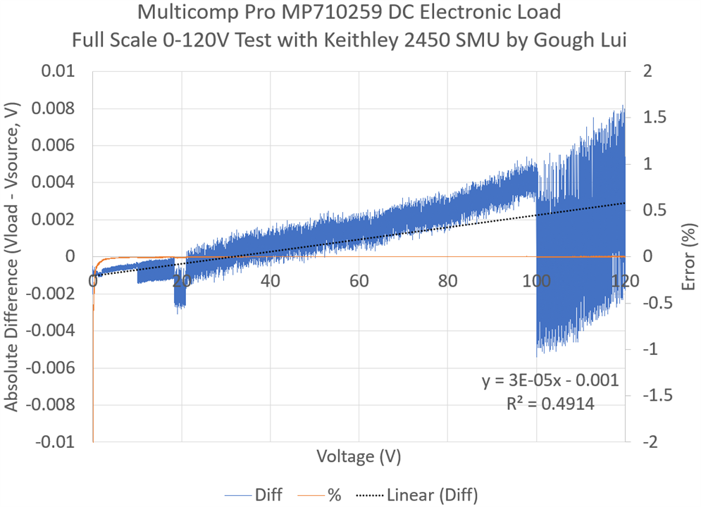
All readings were within around 8.1mV of the value reported by the Keithley 2450 SMU which is the most accurate device in my possession. The increase in noise at 10V is due to the loss of one digit on the meter, while the bump at 18V is due an internal range change on the the load itself. The increase in noise at 100V is due to the loss of another digit. This result is extremely impressive given that the specification is 0.05% reading +/- 0.05% full-scale. Even just the latter term would put uncertainty at 60mV at 120V, or 9mV at 18V, which the load easily beat. This is especially surprising given the unit comes with no calibration certificate (which, usually, would not be a good sign).
Testing of current could only occur up to 1A for the 2450 due to the SMU’s limitations. Testing was performed at 0.5mA steps.
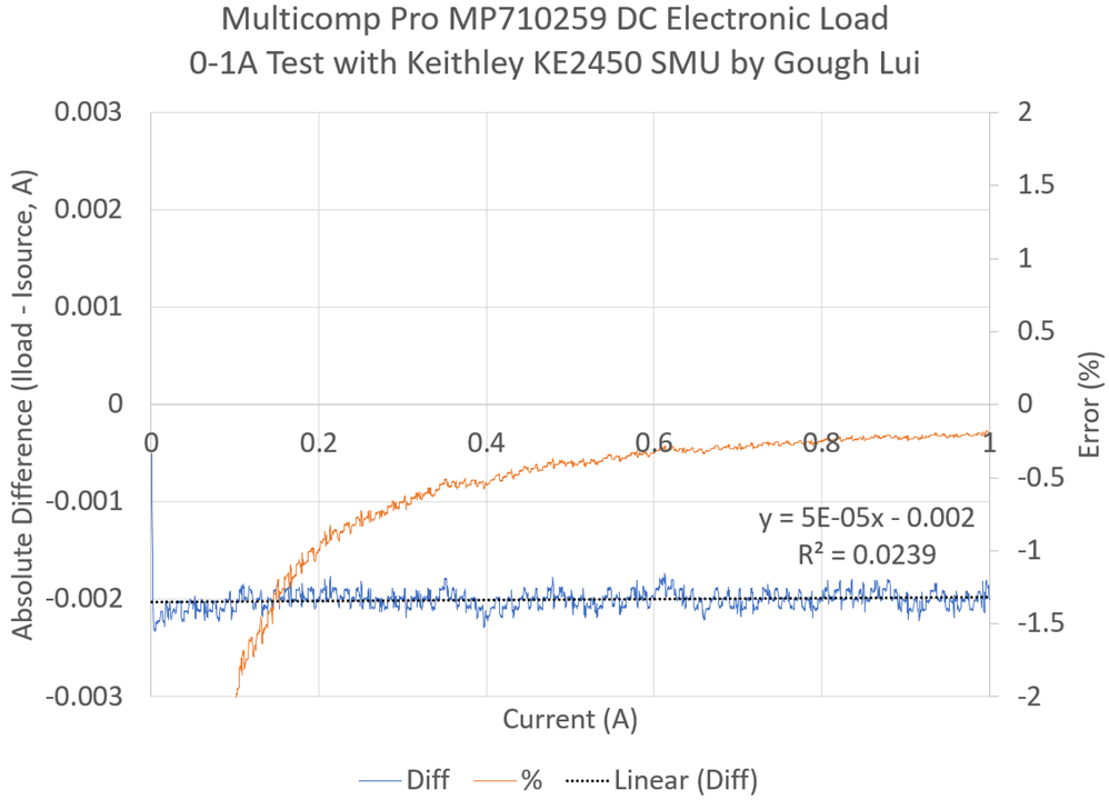
Do my eyes deceive me? As it turns out, I double and triple-checked and this result is right. In the 0-1A range, the load tracks the SMU’s measurement practically identically except for a 2mA offset (underestimation by the load). This error is both small but also so nearly flat that I had doubts as to the validity of the test.
While this may seem to support the 0.05% reading +/- 0.05% full-scale specification at first glance, as at 3A full-scale that would correspond to an error of 1.5mA. Unfortunately, this does mean that for the full tested range, the unit is out-of-spec except for at 1A load, as the 0.05% reading term contributes less than 0.5mV for currents less than 1A. I suspect the specification may be a bit optimistic here and this is the victim of an offset error, but it is easily compensated for if you know the behaviour of the unit. Perhaps better calibration would have helped.
Concentrating on just the low-current values is a bit unfair for a unit that is specified for 30A, so I pulled out the Aim-TTi QPX750SP power supply to give it a full workout up to 30A. Unfortunately, as the supply is only capable of 10mA current setting resolution, the results are limited in their accuracy. I don’t have a meter capable of measuring such large currents, nor do I have an accurate shunt I could use at this time.
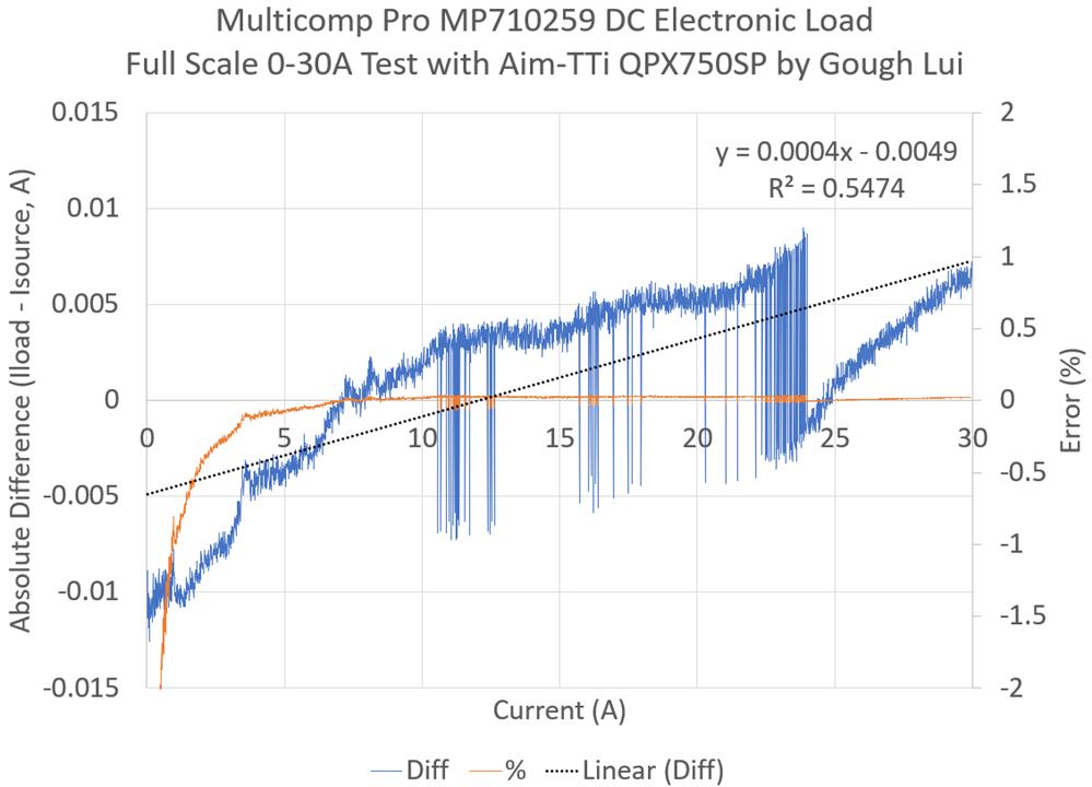
While the graph is a little messy, discrepancies are mostly within 10mA either side of zero. Given the setting and readback granularity of the supply is only 10mA, it should be interpreted that both the power supply and load are in agreement with the current across the full range.
Minimum Voltage for Full Current
As the electronic loads use active silicon semiconductor elements, it is usually not possible to sink the full 30A current until a minimum amount of voltage is developed on the inputs. I attempted to determine this by forcing the unit to sink 30A CC from an Aim-TTi QPX750SP Power Supply while I reduced the voltage until it failed to sink 30A, then raised it back one step.
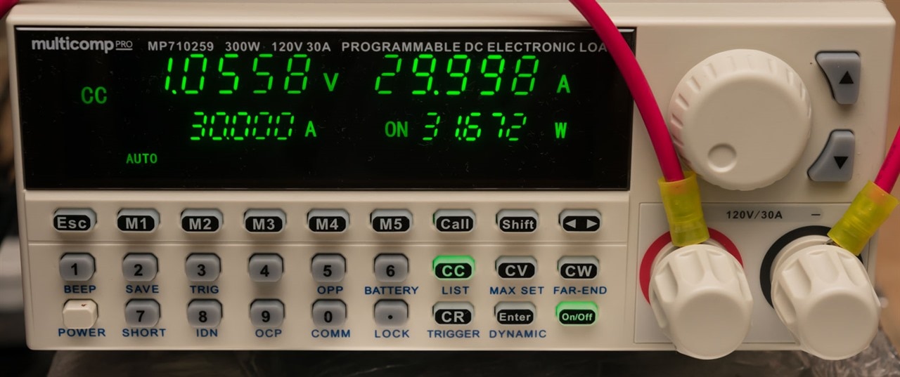
As it turns out, the value is around 1.0558V as reported by the unit. This is very close to the normally-reported 1.1V or thereabouts for most DC electronic loads.
Thermal and Acoustics
As expected, the unit has a fan inside for cooling. The fan is thermostatically controlled and changes speed under load. It is audible, similar to a computer power supply fan, getting somewhat louder and roarier at full load. It doesn’t have much of a “whine” to it, so it is still easily tolerated.
Applying full load for over an hour did not pose any problems for the unit when operating in an ordinary 25 degree Celsius ambient.
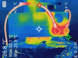

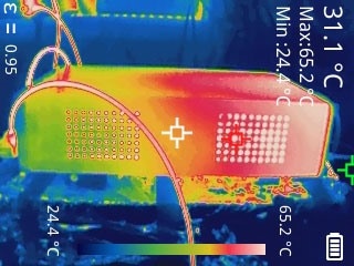
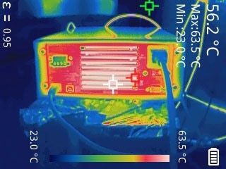
Heat is generally concentrated in the rear of the unit, with no alarming temperatures reported from the Topdon TC004 Handheld Thermal Imaging Camera. The 6mm2 wire carrying 30A turned out to be the hottest thing in some images.
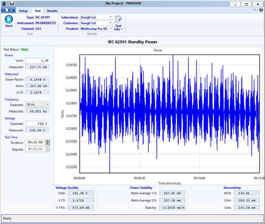
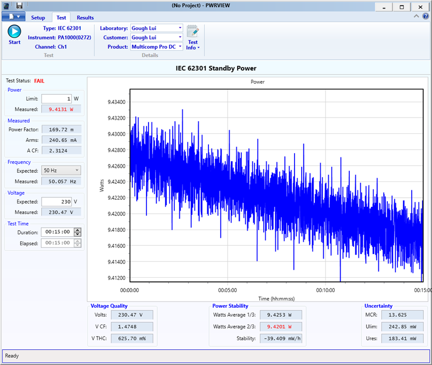
Standby Power Consumption
With regards to standby power as measured with the Tektronix PA1000 Power Analyser – with a mechanical power switch, the unit consumes some power when turned off. This power draw is a reasonable 0.237W and is likely due to power filtering and or a discharge resistor being across the line while the unit is powered off.
When idling, the power consumption was measured to be around 9.4W which is significant considering it is inactive.
Input Off Impedance
A fact of many pieces of test equipment is that “off” is not truly off – that is, even when the output is off, a small amount of current may be consumed from the device under test. I measured the current flow as a function of voltage with the Keithley 2450 SMU both with the unit powered off and with the unit powered on.
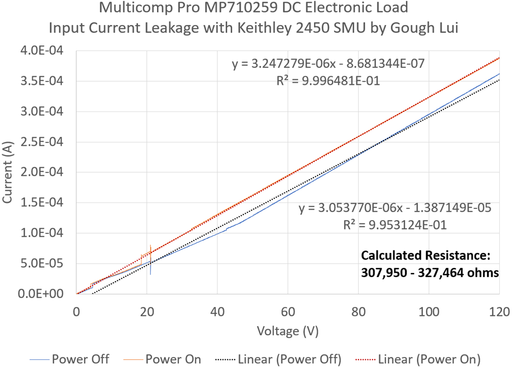
The results suggest an impedance of about 300kΩ, which is a good result and is twice as much as the manual and datasheet suggests. Some of the bumps in the curve are due to SMU auto-zero and range changes, although the one at around 5V and 18V may be inherent to the load.
Other Tests Not Conducted
Unfortunately, I didn’t test the transient generation capability nor the onboard battery test capability. For proper testing of transient generation rise and fall times, I would prefer the presence of an Imonitor output to be fed into an oscilloscope, which this unit does not have. While I could test it by measuring the output current across a resistor, I fear that the results may be skewed because of power source interactions with the load. Furthermore, as mentioned earlier, the front-panel user interface is quite unintuitive to use and I didn’t feel it necessary to master it, especially for battery testing, when remote scripted operation is much more flexible (albeit, perhaps slightly less safe or reliable given its dependency on a functioning remote-control connection to the load). If these modes matter to you, unfortunately, I think you’ll have to do a bit of testing yourself …
Conclusion
The Multicomp Pro MP710259 Electronic Load was a pleasant surprise to me. I have (secretly) always wanted to try a Korad KEL103 myself, but never had a good reason to pull the trigger on it as the B&K Precision Model 8600 has done most of what I needed of it. Now that I have this rebadged unit, I can definitely say that it surpassed my expectations (given the price and lack of calibration certificate) when it came to accuracy. This was the case even at low currents, when it appeared to miss the specifications somewhat due to offset error (which could be compensated for) as the gain error was virtually zero. In the end, the overall accuracy seems well within my needs for most of the experiments I have used other loads for. While not all features were tested, the important constant current mode and constant voltage modes definitely worked well and remote-control connectivity was very reliable, once it had been set-up correctly and with some software magic.
The key downsides would be the quirky broken DHCP and MAC address on LAN which could cause problems when multiple units are on the same LAN, the use of UDP which makes it incompatible with all VISA layers, the way it interprets commands inconsistently and implements an incomplete command-set, and the fact it responds with units appended to numerical value queries. This all caused headaches as it meant that the unit won’t work without some workarounds and careful configuration. After a few hours developing my crude but valuable Python-based LAN proxy, most of these issues are overcome for basic use. The 7-segment display based user interface is quite cryptic due to the limited characters available and the multiple-function nature of each button. The user manual and documentation are very important for this, but in all respects, are very basic and difficult to understand at times, lacking many pieces of key information which may cause some users frustration.
However, when one considers the price of this unit being about a quarter of that of a B&K Precision product with only half the power handling capacity, it would seem that economic sensibility would make the choice of the Multicomp Pro MP710259 a proverbial “no-brainer” as long as one is willing to live with or work around the shortcomings. Will it be as reliable in the long run? It is hard to tell.
As of now, I’m still awaiting the official word from element14 regarding the damaged unit and what to do with it. If they don’t want it back, then I’ll be happy to do a teardown, see exactly what happened and try a repair and see how it fares. Perhaps it too could be saved, rather than headed to landfill … especially now that I know this unit is quite decent.
But perhaps now ... I should really find some time to participate in the Experimenting with Flyback Transformers Design Challenge ...
Top Comments