


It’s been a few months since I delivered my Keysight Smart Bench Essentials RoadTest Review. While I had done as much as I felt was possible within the two-month period, there were a few loose ends that I promised to follow-up later.
Time got the better of me as I worked to get back on-track with the Experimenting with Current Sense Amplifiers Design Challenge after being sent interstate. In-between, I found myself lamenting the fact the review seemed to have disappeared from the Recent RoadTests view and from My Content in my profile, seemingly due to a bug in the site that still has not been resolved.
Only now have I managed to find some time to document some of those loose-ends and the results of some investigations into the unexpected.
DSO Channel Noise
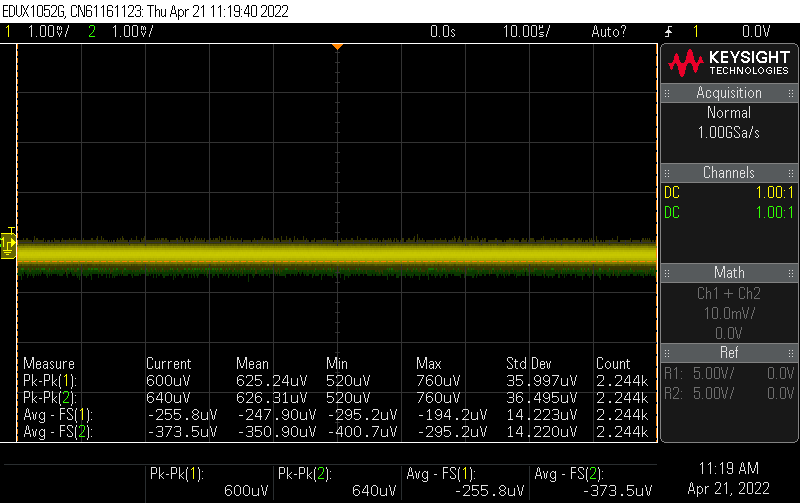
One thing I noticed when attempting to measure the oscilloscope channel input noise was that I had the input bandwidth limited somehow. It turns out this was a case of not reading the fine-print, as it seems using the lowest vertical scale automatically engages the bandwidth limiting function. Repeating the test at the next-lowest vertical scale provides a more accurate representation of the front-end’s capabilities which is a little bit noisier, but seemingly in the expected ballpark (~625uV p-p at 1:1, which would translate to 6.25mV p-p for 10:1).
DSO Hacking?
I think it’s probably no big secret that the Keysight Infiniivision oscilloscopes have long been the subject of various modifications and hacks to improve bandwidth and functionality. While this is definitely against the wishes of the manufacturer, it seems that individuals doing so have met various levels of success at their own risk.
As someone with a lot of scopes to choose from, I thought it would be interesting to see if the hacks documented for the 1000X series could be applied to the “related” EDUX1052G. The first thing to notice is that the new instruments seem to be Linux based, as opposed to the earlier Windows CE-based counterparts, so firmware/software hacks seem out of the question. Hardware hacks, however, still seem to be a possibility.
A quick search online turned up this post which listed the strapping IDs for this family. As an EDUX1052G, this unit would have an ID of 35. From the family, the logical “upgrade” would be to the DSOX202G which would unlock more memory and bandwidth up to 70MHz. A bit more looking around seemed to suggest the following strapping resistor configurations to be likely valid.
Tearing the unit apart again, I did identify the strapping resistors – although the ones on the board appeared to be a tenth the value listed on the posting. This is no issue, as they function as voltage dividers and only the ratio matters. It is just our luck that changing the 5 to a 3 just means swapping the top and bottom resistor of the second digit – which I managed to achieve.
After performing the modification and restarting, it seemed to have the increased bandwidth and memory, but retaining its original ID. However, it wasn’t entirely successful as the channel buttons and knobs for the math and regular channels did not function as expected, calling up other functions instead. Trying the button test feature, pressing all buttons, I was not able to activate those controls after the modification was done. I suspect this means that the front-panel matrix connection must be different between models despite having the same keypad layout, but I didn’t feel it worth the effort to try chasing that down. I suppose if one always uses the oscilloscope via the remote front-panel, that would be acceptable, but I just couldn’t see that happening for me.
In the end, I’d have to recommend that users don’t try this on their EDUX1052G. Not having a properly functioning front-panel interface is very frustrating, but furthermore, the whole procedure is quite involved and risks damaging the unit. The SMD resistors involved are very tiny – losing them or damaging them would make for a very bad day! Furthermore, the small bandwidth increase is very marginal, although the increased memory would be nice. In the end, I reverted the resistor configuration to the original and called it a day. There may have been a way to make it work … but frankly, I couldn’t be bothered to invest any more effort to try and track it down.
Post DMM Teardown Accuracy
If there’s one thing I’ve been told repeatedly, it’s that test equipment can be quite sensitive and need to be “calibrated” regularly to maintain accuracy. Another is the fact that one shouldn’t open the enclosure of such equipment, as doing so will affect the calibration by such trivial things as how tightly the unit is screwed together.
The DMM is the most precise instrument of the suite, and was completely torn apart in my review, so it would be nice to see just if the adventure had ruined the DMM for good, or if I got lucky with my careful tinkering. To do this, I repeated the calibration checks that I performed in the instrument performance test chapter.
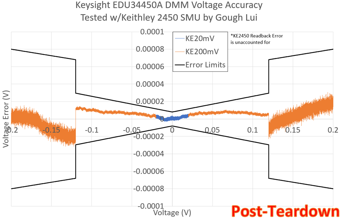
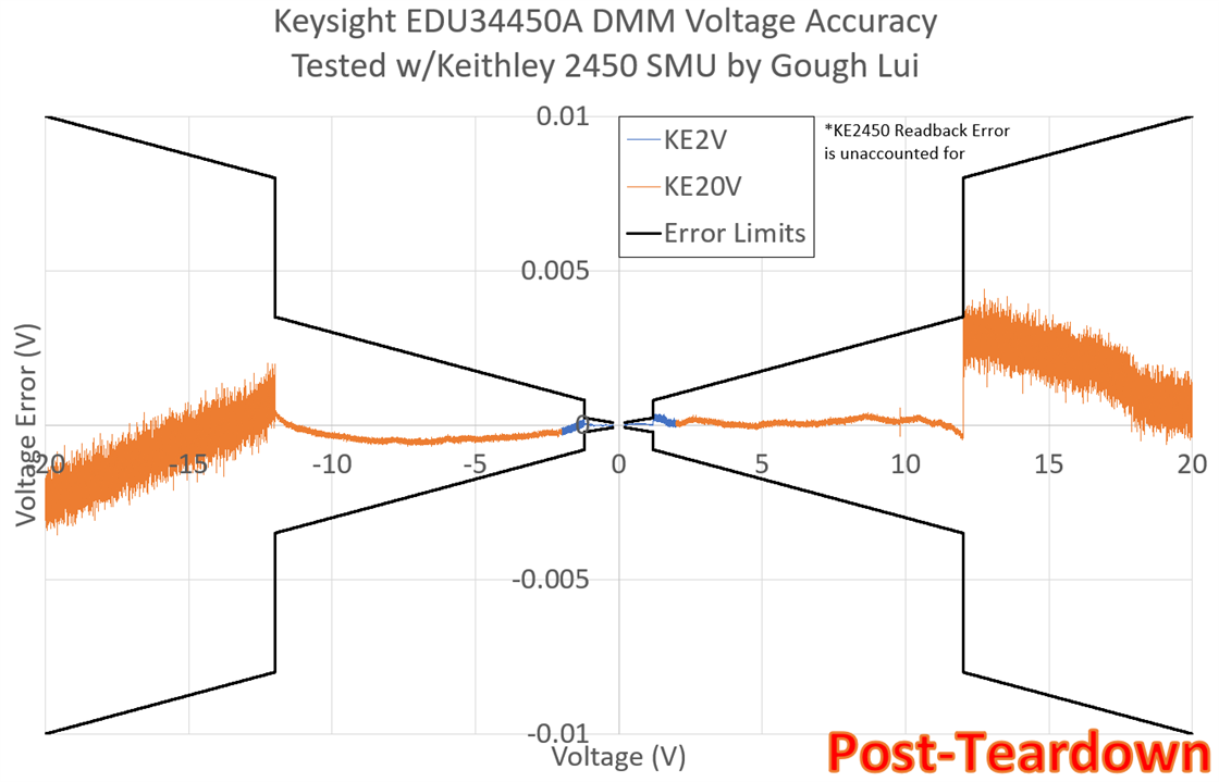
Voltage accuracy appears to be within specifications and is quite similar to the result pre-teardown.
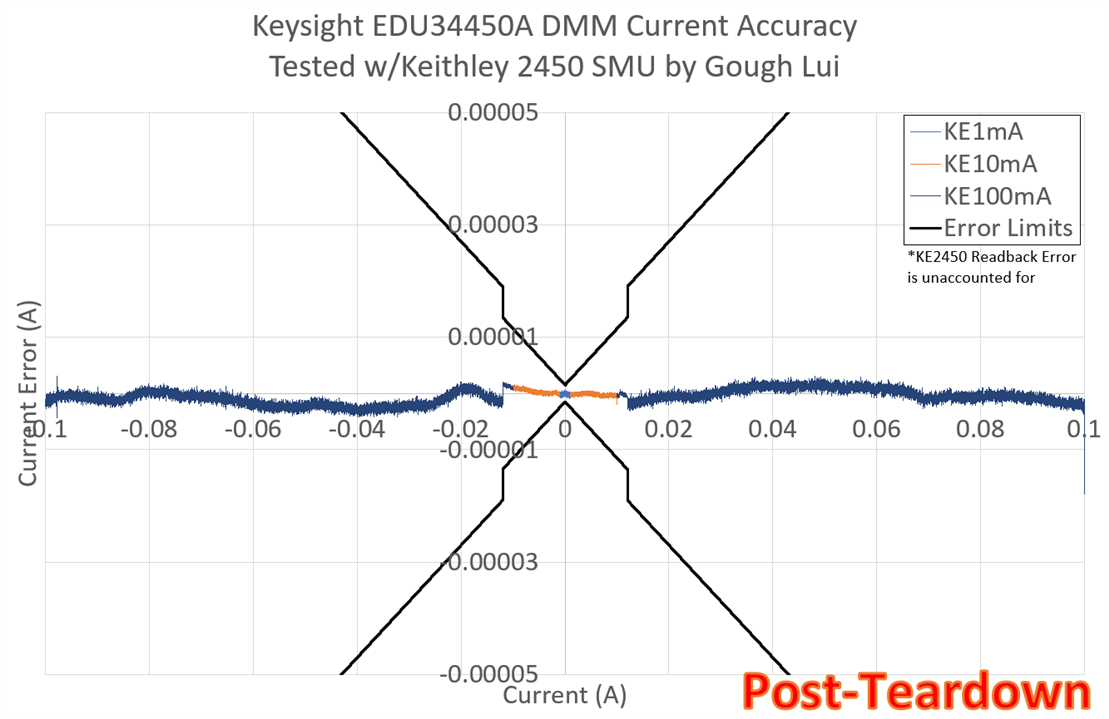
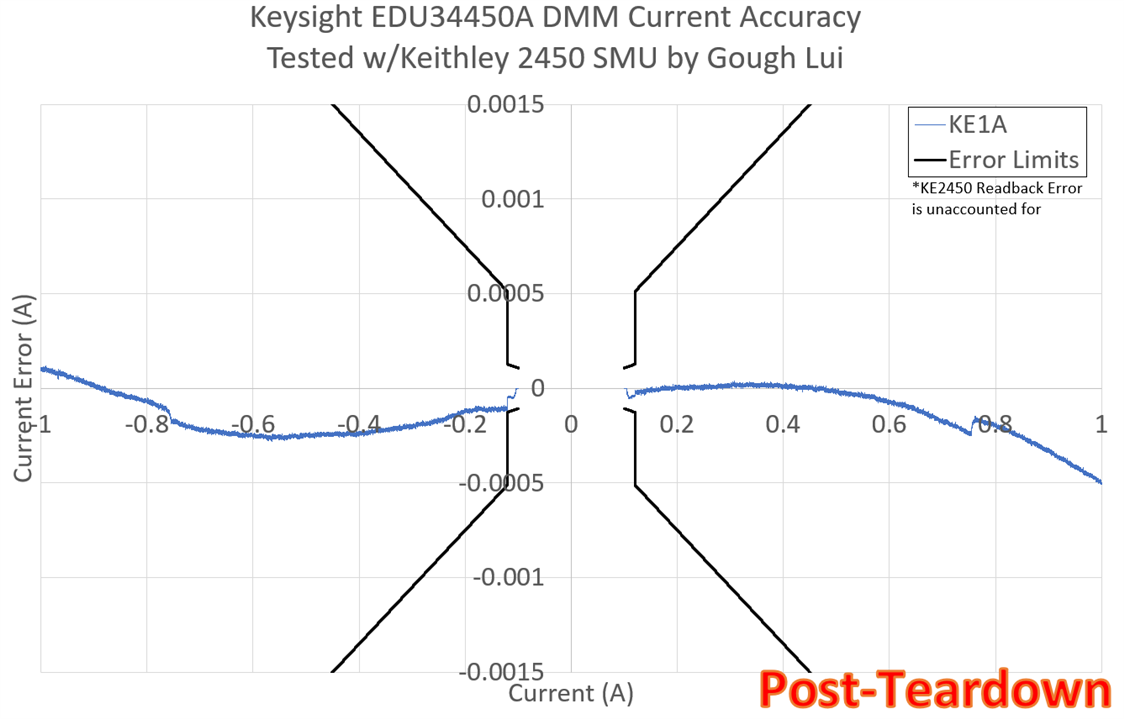
Similarly, current accuracy seems to be well within specifications and is marginally better than before the teardown! Perhaps I managed to improve the meter, or perhaps the slight difference in test temperatures affected the result, but it seems the meter has not really suffered as a result of the teardown.
Accuracy of 100V/1000V DC Range
One aspect of the performance and calibration that I did not post about in the original review is that of the 100V/1000V range which I tried to test using the Keithley 2450 SMU as the results appeared anomalous. The first thing I decided to do was to check my code and repeat the experiment post-teardown just to see if the result got any better.
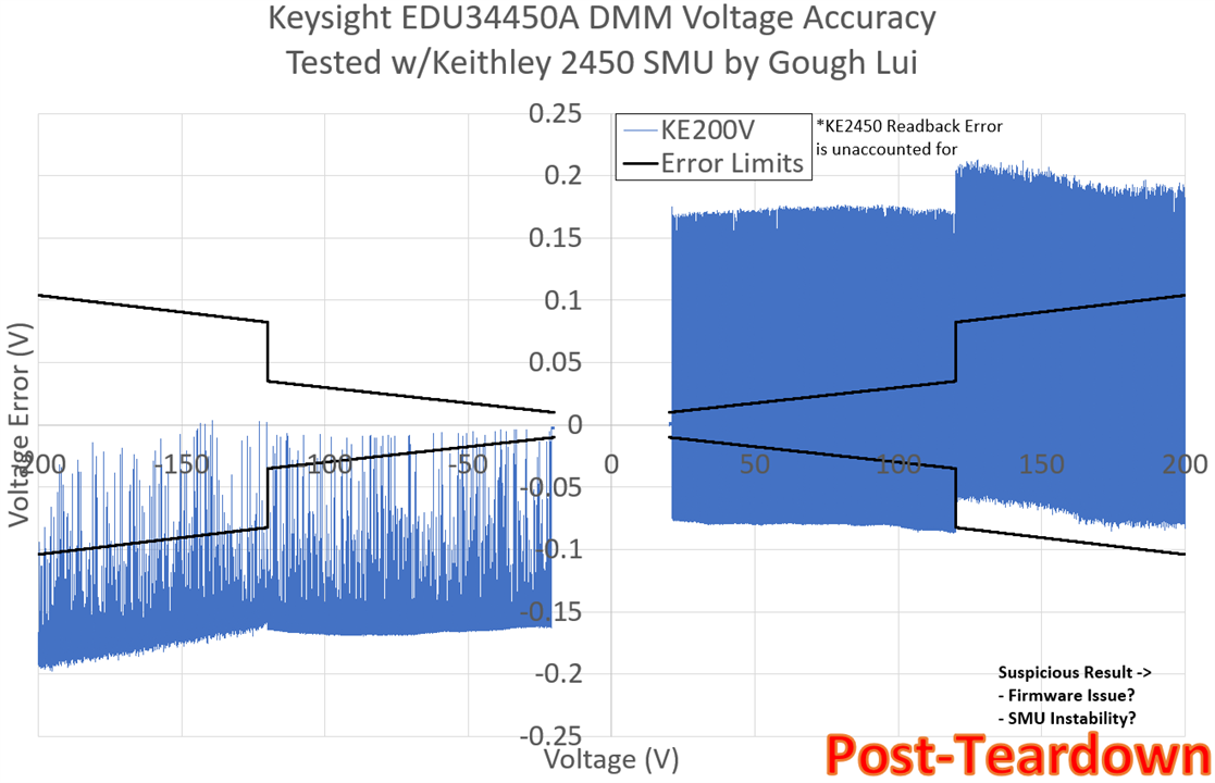
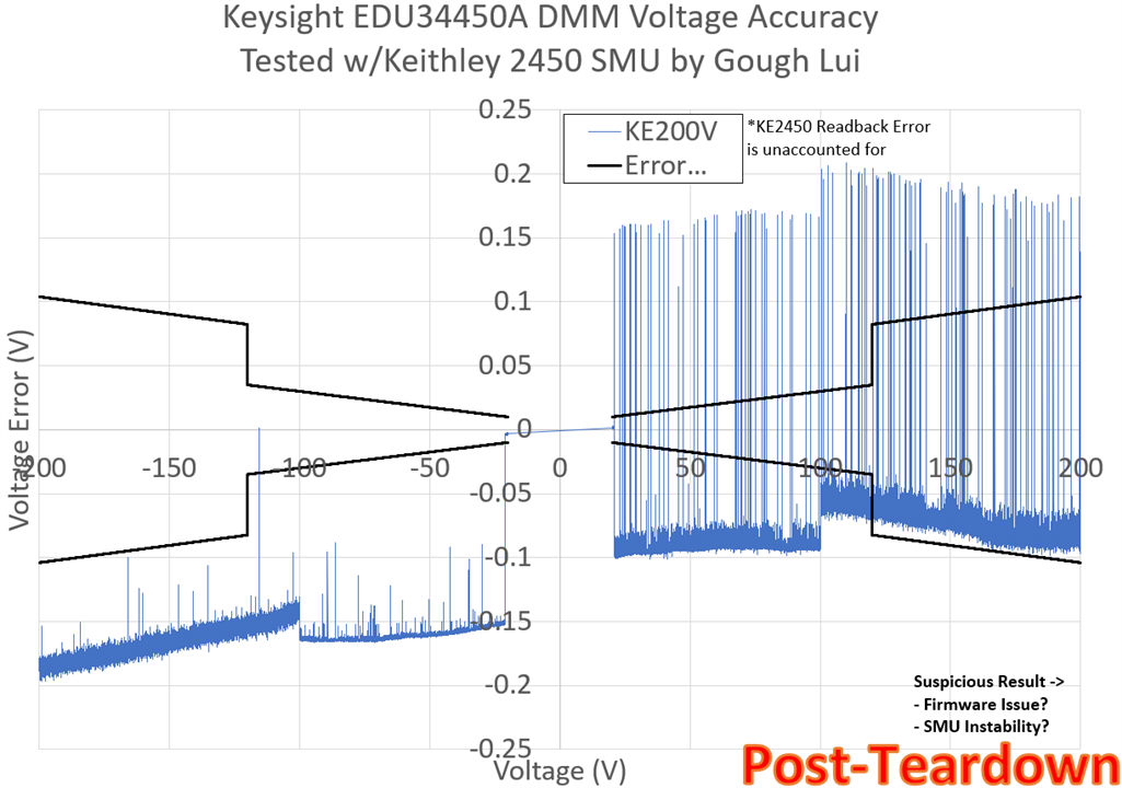
The result I obtained was this noisy and confusing plot which seemed to suggest the reading was very noisy and differs depending on the voltage being positive or negative. However, a quick examination seems to suggest this result is not because of the Keysight EDU34450A.
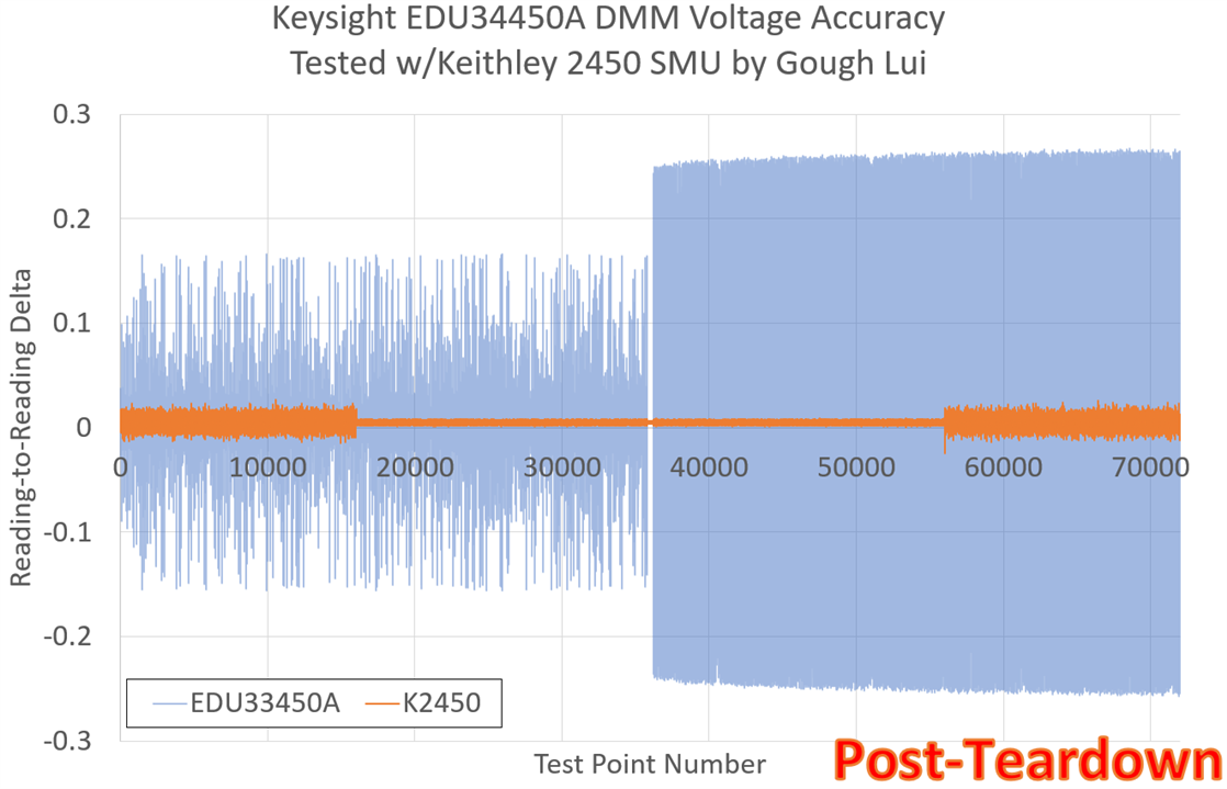
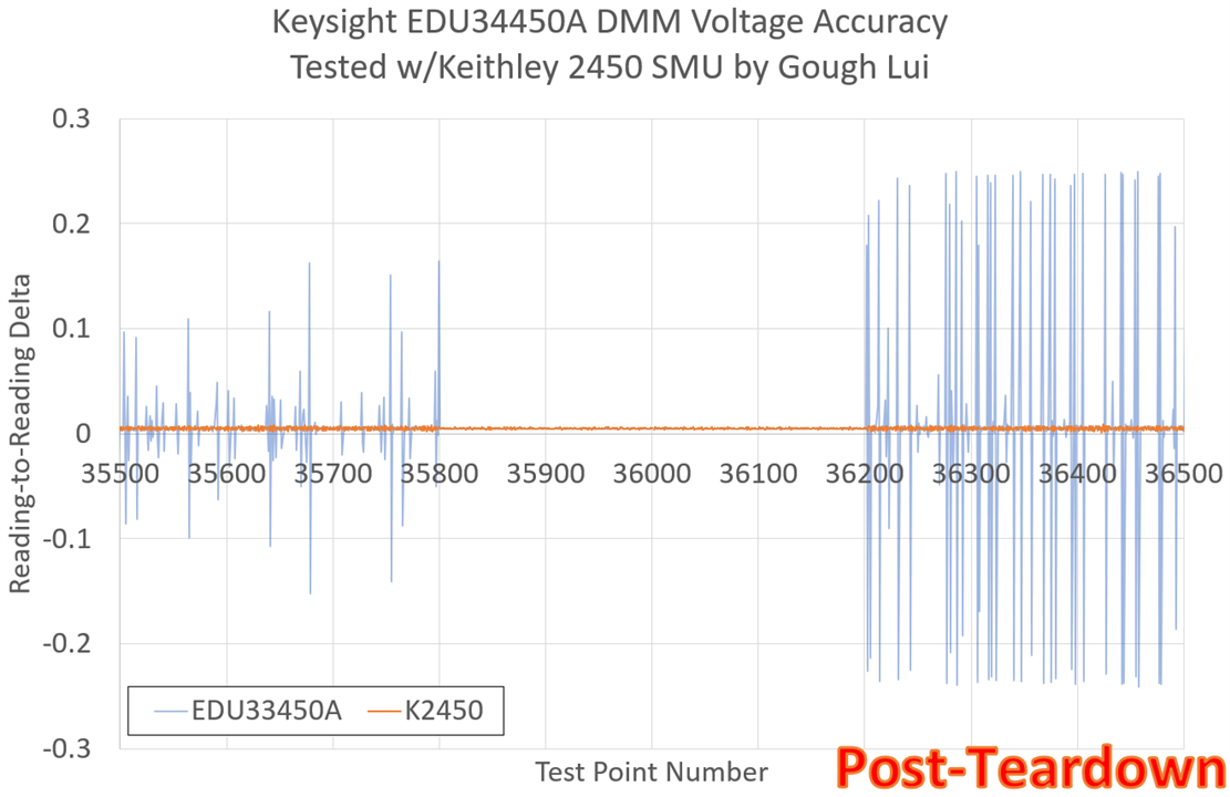
I took the SMU’s read-back values and took the delta between two steps. This should result in a constant value (or very close to it). Instead, it did not, and had a spiky amplitude of about 0.25V in the positive part. Looking into the middle values, it can be seen that the spikes seem to quiet down – this corresponds to the 20V range values, with the spikes appearing in the 200V range data only. Doing the same with the DMM data in orange, showed no such spikes!
Given that I previously had to send the Keithley 2450 SourceMeter back to the USA at my cost for repair and recalibration because of a manufacturing issue, it seems the 200V range on my unit seems prone to be problematic. It’s not even been two years since the repair!
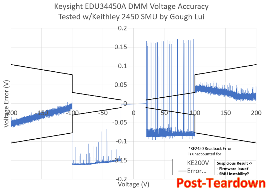
Perhaps this is not fatal, I thought, so I turned off the 2450, let it cool down and switched it back on to re-run the experiment. This time, there were fewer spikes, but the same issue cropped up again.
The strange thing was that the result on the DMM seemed to match the requested value from the SMU, but the SMU was not measuring its output correctly. Perhaps this is a sign that the SMU was unstable and oscillating.
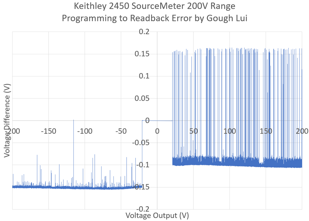
Plotting the programming minus readback value shows just how out-of-whack the SMU’s own metering seems to think it is. But I’m convinced that the output is pretty much correct in-spite of this. I could just plot the EDU34450A’s reading versus the programmed SMU value, but that would not necessarily be correct.
Nevertheless, I decided to give it one more try, but this time I would manually switch the DMM’s and SMU’s ranges rather than letting them auto-range and also bring in the Keithley 2110 5.5-digit DMM as a second-opinion just to be sure.
This time, the same spiky behaviour is seen between 20-100V output, but when the DMMs were manually kicked over to 1000V range, it seems the SMU may have settled down just fine and the values became in-range again.
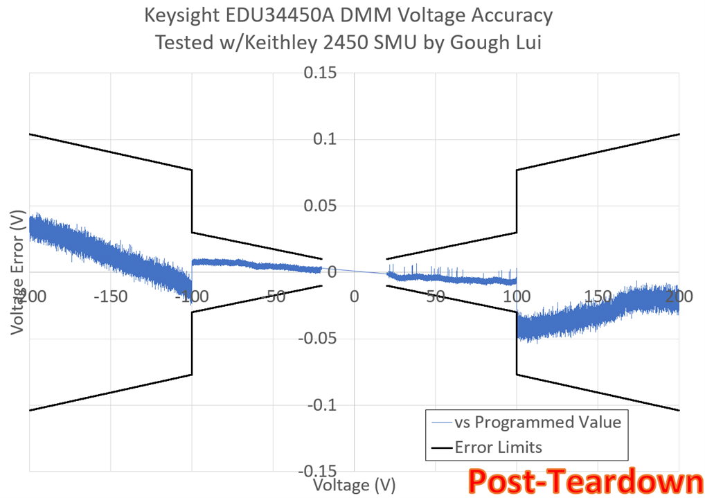
Comparing the measurements from the EDU34450A and the requested value from the SMU gives a good image showing the readings are within the datasheet specification limits.
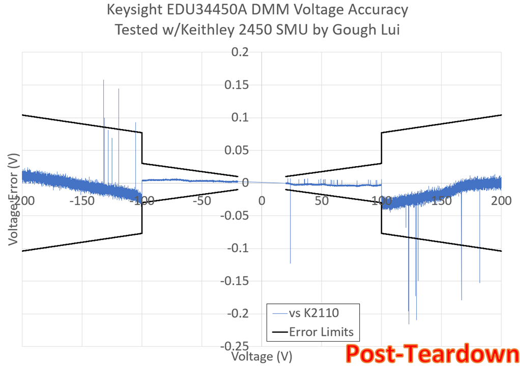
Comparing the readings from the EDU34450A and the Keithley 2110 5.5-digit DMM gives a very similar answer – it is pretty much within specification. The reading from the Keithley 2110 does have a few spikes here and there – perhaps the SMU really was oscillating, or the 2+m test leads were picking up some impulse noise.
In the end, the Keysight EDU34450A digital multimeter was just fine after the teardown, and it seems that even up to 200V, the readings are within the specified accuracy. Instead, it discovered that my Keithley 2450 SourceMeter was misbehaving – a regrettable outcome I did not expect. I will need to be more careful of using the 200V range on that unit from now on – it just doesn’t seem to be all that reliable … at least with the metering.
BenchVue Software Updates
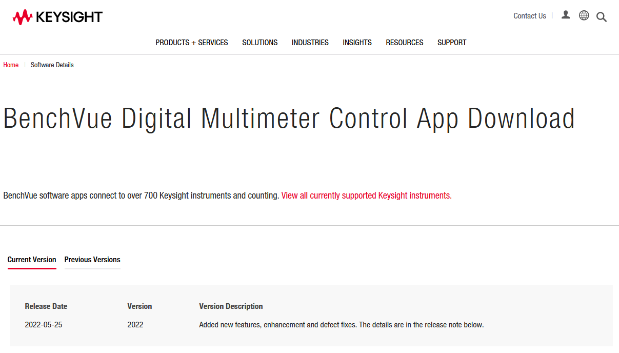
Since the completion of the review, two of the Pathwave BenchVue applications have received updates. The Power Supply and Digital Multimeter apps both are now at version 2022, with most of the changes seemingly being “under-the-hood” and improvements for regionalisation.
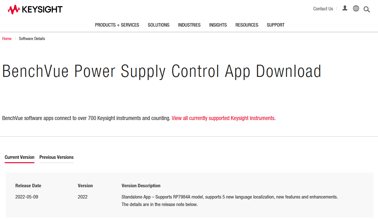
I first tried the Power Supply app which seems to now sport BenchVue TestFlow integration without the need to find it in a “hidden” menu. Now, once enabled, it highlights certain sections of the screen in orange to indicate controls which can be connected to TestFlow. Unfortunately, I was not able to make this connection work – dragging and dropping some blocks allowed them to appear in the flow, but I couldn’t get the output switch blocks to work at all.
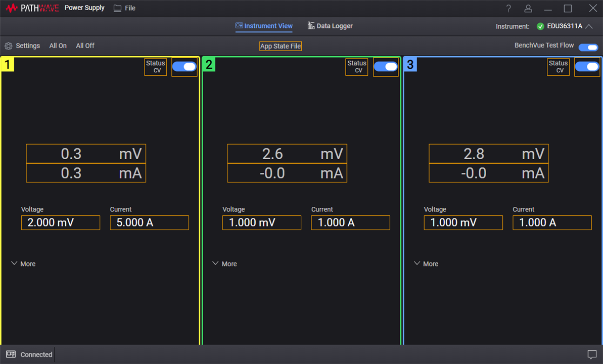
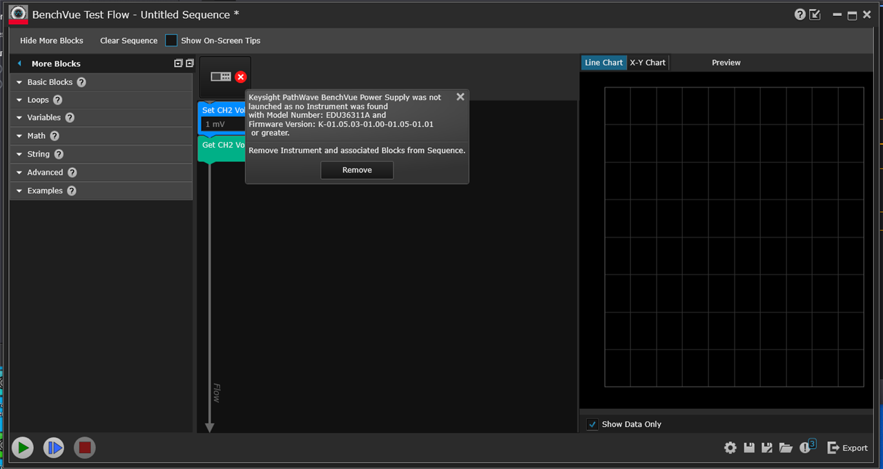
Attempting to run the flow also results in an error connecting to the instrument. Perhaps somehow my BenchVue and PathWave BenchVue just can’t talk to one another … but I don’t believe I have anything specific to my installation that would stop it (e.g. a firewall).

There was a subtle change to the green “tick” icon when an instrument is connected, although this is mostly inconsequential. The graphing module apparently has been improved too, but I still find it awkward to use.
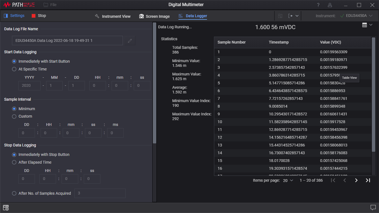
The Digital Multimeter app looks pretty similar – perhaps I missed it before but it seems there is a data table option. Unfortunately, using the graphing while it is logging is still relatively slow and the timing figures seem to dance around for the existing datapoints which are already logged, which doesn’t make sense to me.
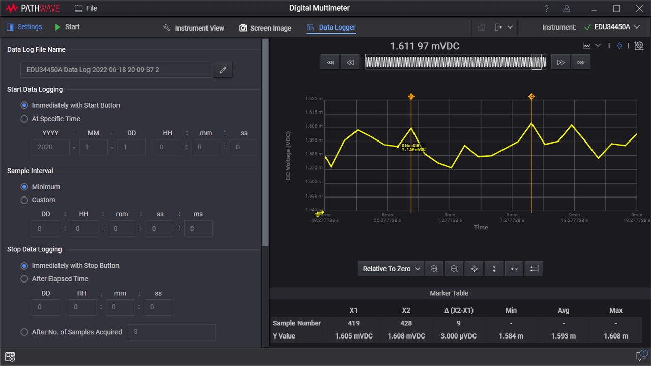
Perhaps a new improvement is the cursors, but I still find the graphing to be relatively tricky to navigate and use effectively compared to exporting data for a third-party tool to analyse. It doesn’t seem BenchVue TestFlow integration has made it to the Digital Multimeter app just yet.
One thing I did notice if I ever used the data-logging functionality on the DMM was that the data doesn’t seem to be able to be cleared from the instrument, so the MEM indicator stays on the screen.

Unfortunately, the BenchVue app doesn’t seem to interact with the memory on the DMM, and there is no web-based SCPI terminal, so the only way to clear it is to issue DATA:DEL NVMEM from the I/O Suite or a VISA program of your own.
Conclusion
In the end, my conclusions from the review have not changed, although it seems some progress is slowly being made with regards to the Pathwave BenchVue apps. I think there is still quite a bit of room for improvement in terms of making it as responsive, flexible, versatile and easy-to-use as I would have liked, but I suppose my needs could be greater than those of an average user.
With regards to hardware, I’d have to say that the Digital Multimeter and Waveform Generator will probably stay with me at home as they’re very handy to have around. Since the review, the oscilloscope has been taken into my workplace where it now serves as a secondary unit for my colleagues to use, while the power supply could see a similar fate, but still remains with me at this time.