


My original review of the Rohde & Schwarz RTM3004 Oscilloscope went up in July 2018, which identified a number of bugs and functionality issues with the V1.300 firmware that was current at the time. I dutifully reported the issues I had encountered to the representative, who forwarded it up the chain with a promise that a new firmware would be coming “soon” to resolve some of the issues.
As it turns out, “soon” is a rather relative term. I was expecting possibly in a few months, but instead it had turned into six months. Regardless, according to the website, a new firmware dated 17th January 2019 with V1.400 was made available and I was able to download it 23rd January 2019 to give it a try. Owing to the number of changes, I thought it would be worthwhile posting an update blog.
The new firmware and changelogs can be downloaded from your local Rohde & Schwarz website, noting there are two versions of the firmware – the US version and the non-US version. Much of the following tables has been excerpted from the Rohde & Schwarz changelog document and brochures.
New Firmware Changes
According to the changelog document, the new firmware includes the following changes:
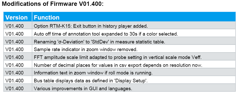

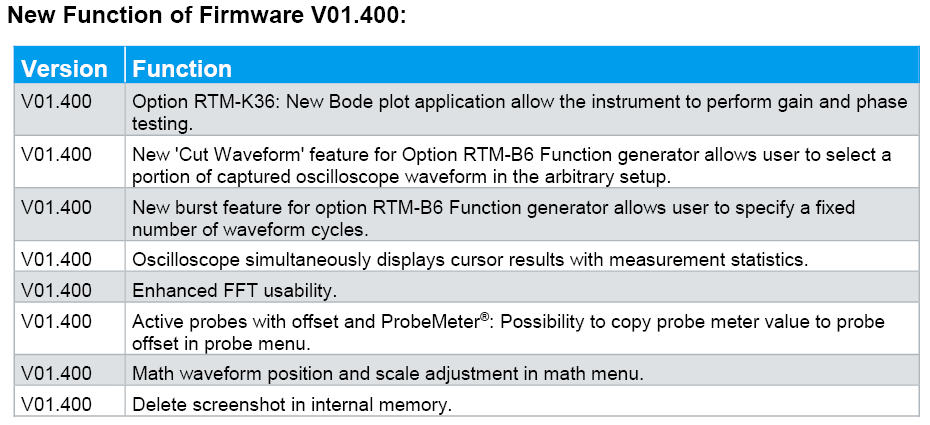
Some of the changes do directly address the issues I had identified, although the lack of detail in the changelog (e.g. “Various improvements in GUI and languages”) makes it a little difficult to identify precisely what had been done. The biggest issues in my opinion relate to those labelled “firmware blocker” which caused the unit to lock-up when those operations were performed.
Firmware Upgrade Process
To upgrade the firmware is a simple process that takes only a few minutes. After downloading the .ZIP file, decompressing the appropriate .FWU file and copying that to a USB memory key …
… it’s a simple process to insert it into the RTM3004 and navigate through to the Firmware Update menu and apply the update.
User Experience & Other Changes
I’m happy to report that the vast majority of the functional bugs I reported have been addressed by the V1.400 upgrade. This includes:
- Caption wouldn’t always update upon changing text – much improved, now it seems to work most of the time although it seems caption length can be an issue (31 characters best case, 16 characters worst case) and only one caption is currently supported.

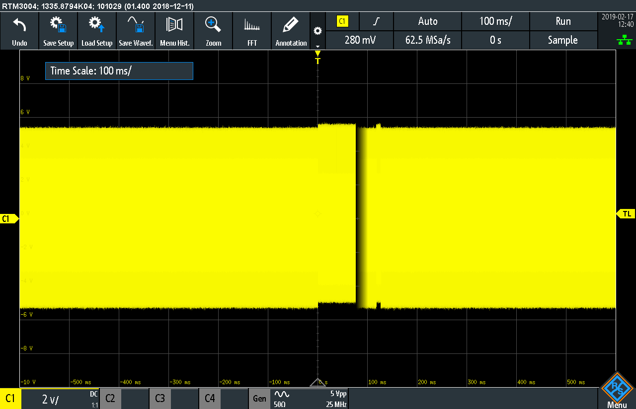
- Aliasing would occur at longer timebases with a high-frequency signal even with sufficient sampling rate or using peak-detect modes – now fixed and displays the right result.


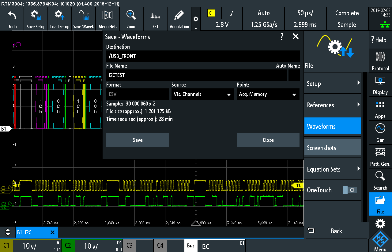
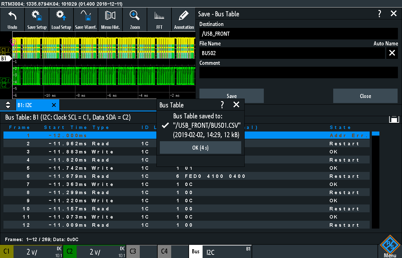
- Exporting Visible Channels or Bus Table export with more than one line would cause lock-up – now fixed and improved with a save progress containing estimated time.


- It was possible under certain network conditions to cause the oscilloscope to lock-up – this issue now fixed.
- Keyboard defaulting to QWERTZ - now fixed and defaults to QWERTY making things good for those with US/International keyboards. I didn't look for an option to change this back, so maybe the EU countries may lose out as a result of the change.


Some of the more minor issues I reported with the display of custom UART rates, self-alignment instruction text, labelling of demo applications still remain, however, these issues are cosmetic in nature and doesn’t affect the functionality of the unit. I haven’t used the firmware extensively enough to spot whether there are any new issues, but having the previously identified issues fixed makes upgrading highly worthwhile.
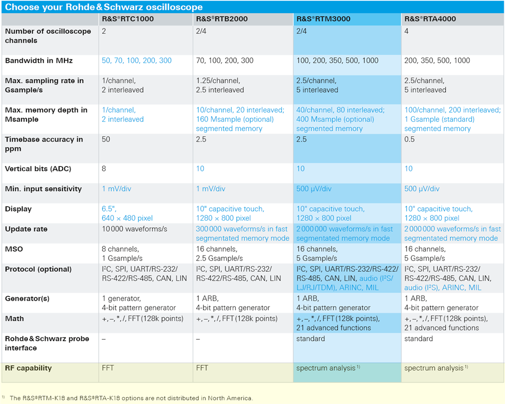
Unfortunately, it seems that access to the K18 Spectrum Analysis feature is still restricted in North American markets according to the current brochure.
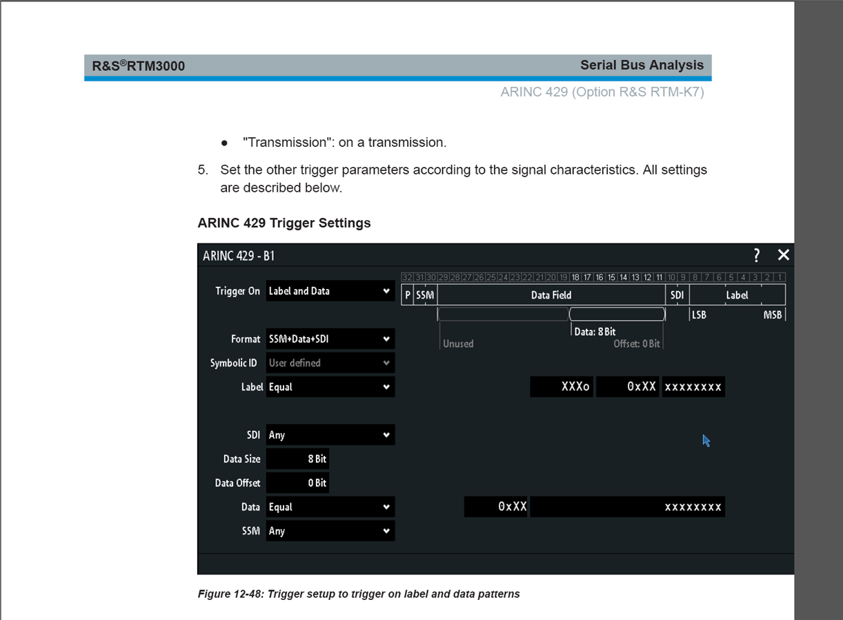
While the manual has been revised to be even more comprehensive with many errors fixed, Version 5 does not appear to cover the K36 Bode Plot option and there are some image formatting issues with the ARINC 429 chapter. I suspect this will be fixed in the next update.
K36 Bode Plot Analysis Option
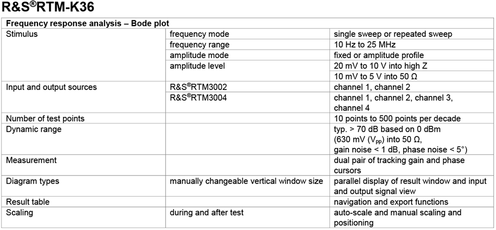
The K36 Bode Plot Analysis option adds the ability for the oscilloscope to perform frequency response analysis in a standalone manner, using the onboard function generator and oscilloscope channels. This application does not require the function generator option to be purchased and is able to characterise from 10Hz to 25MHz at up to 10V into a high-impedance input. It claims to have a typical dynamic range of >70dB with gain noise <1dB and phase noise <5 degrees.
The specs do not seem to be too confident (<1dB/<5° is pretty wide), although I suppose this is because this also depends on the probe performance/compensation, ADC performance and the individual unit calibration. While there doesn’t seem to be a manual chapter referencing the option (yet), Rohde & Schwarz have also put a comparison table pitting the K36 option against the Keysight FRA option.
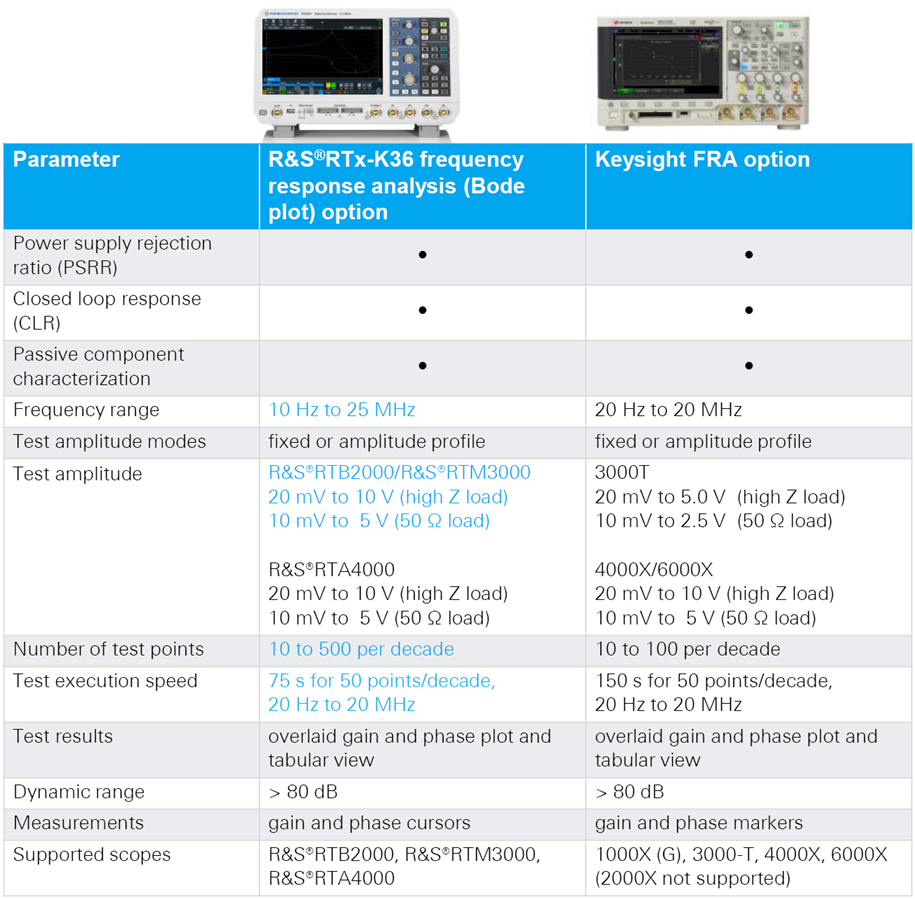
It seems as if the K36 option is in no way lacking compared to the FRA option, although I haven’t done much looking into what other competing bode plot analysis options might be available. It is much simpler than having a separate signal generator and oscilloscope and attempting to coordinate them through SCPI.
Enabling the Option
Thanks to the efforts of the Rohde & Schwarz representative and customer support, I was given the appropriate license key to unlock the K36 option for testing. To enable it, a relatively long string of numbers needs to be entered into the Options dialogue. At first, I entered this incorrectly which resulted in an error. I retried again, entering the number correctly this time but still receiving the error. The option was, however, applied despite the error (which I have reported to R&S for possible investigation).

Configuration
The bode plot module has a number of configuration options which are relatively self-explanatory.
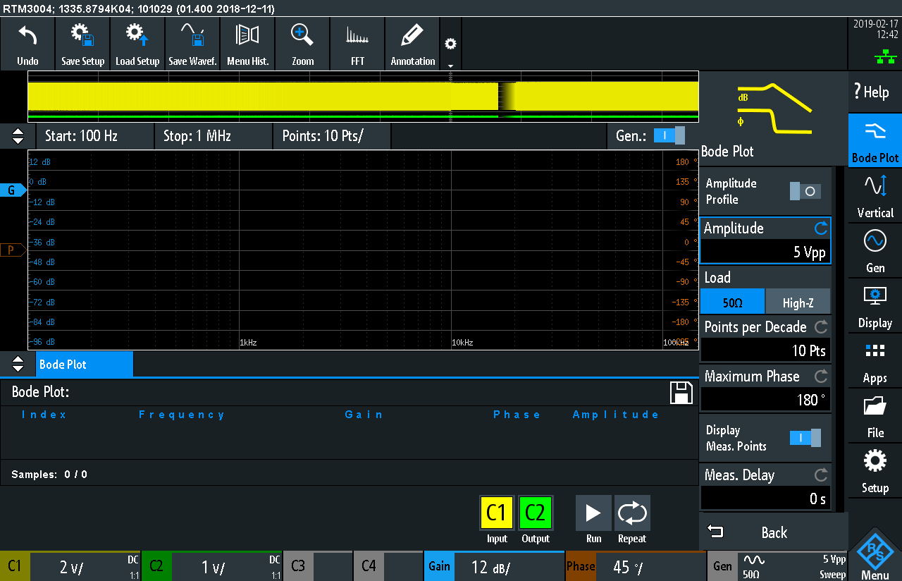
By default, the bode plot can be run in fixed amplitude mode. The load option controls the signal generator settings, with the points-per-decade being configurable to provide a test-speed/plot-detail trade-off. The maximum phase is configurable, along with a measurement delay. The start and stop frequencies can be configured by tapping on the fields above the bode plot.

If the amplitude profile option is turned on, up to 16 profile points can be defined as pairs of frequency and amplitude for more fine-grained control of testing parameters.
Tests can be run from the screen or via network remote front panel control (as above). The plot is drawn as the test runs, with a progress bar in the top right giving a good indication as to test progress.
Experiment: Probe Testing and Cross-Talk
The first thing I thought to do was just to test what the channel cross-talk between C1 and C2 was with the bode plot feature. This would give me a good idea as to what dynamic range to expect (i.e. where the noise floor is).

As the crosstalk signal isn’t clearly resolvable on the other channel with no probe connected, the phase diagram jumps around all over the place. The noise level measures below -100dB, so values above that will likely show “real” signal.
The second check was to see what the result of a direct connection of C1 and C2 is – using the two passive probes (if properly compensated) should show a flat profile in amplitude and phase.
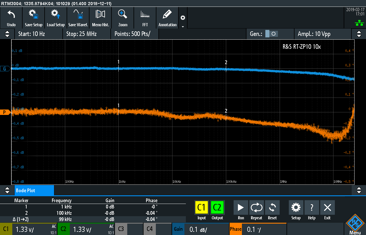
While it’s not completely flat, the amplitude deviation between the two probes is <0.1dB and the phase deviation is about 0.2°. That is a lot better than the claimed <1dB and <5°, thus giving me a bit more confidence in the results.
Experiment: EEVBlog HVP-70 vs Micsig DP10013 High-Voltage Differential Probes
Knowing that the K36 option actually works quite a bit better than expected was a good result. But then I thought, how would I apply this to test something realistic?
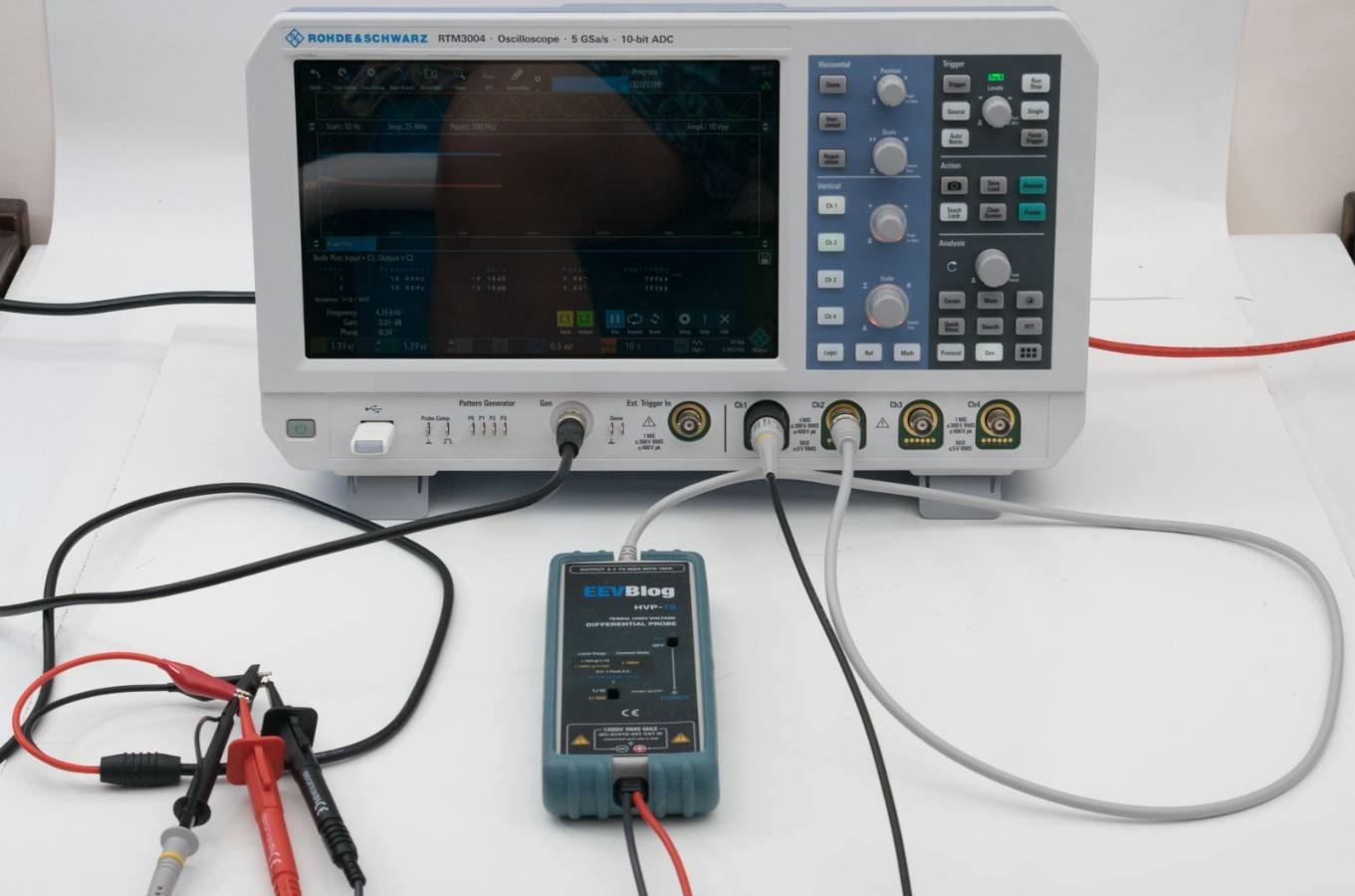
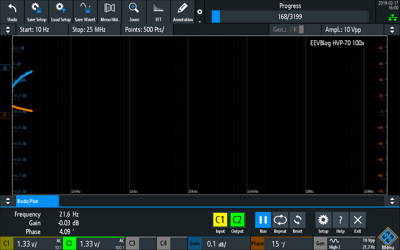
I recently acquired two high-voltage differential probes and did some basic testing for a review. One thing I did not test was the frequency response. While the HVP-70 claims 70Mhz and the Micsig DP10013 claims 100Mhz which are both far in excess of the 25Mhz capability of the K36 option, I still thought it would be good to test their frequency response characteristics anyway.
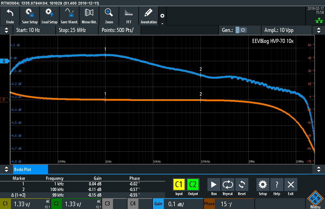
With the EEVBlog HVP-70 in the 10x position, the frequency response is generally quite good, measuring within around 0.1dB up to 100kHz, deviating by <1dB up to 25MHz. The phase is mostly around 0, deviating above 1Mhz. This might not be too surprising as the HVP-70 was similar in design to a 25Mhz unit from Sapphire.

At 100x, the performance was a little less consistent, deviating by a maximum around 1.2dB, but this is still well within expectations and still mostly smaller than the claimed margins of gain error.
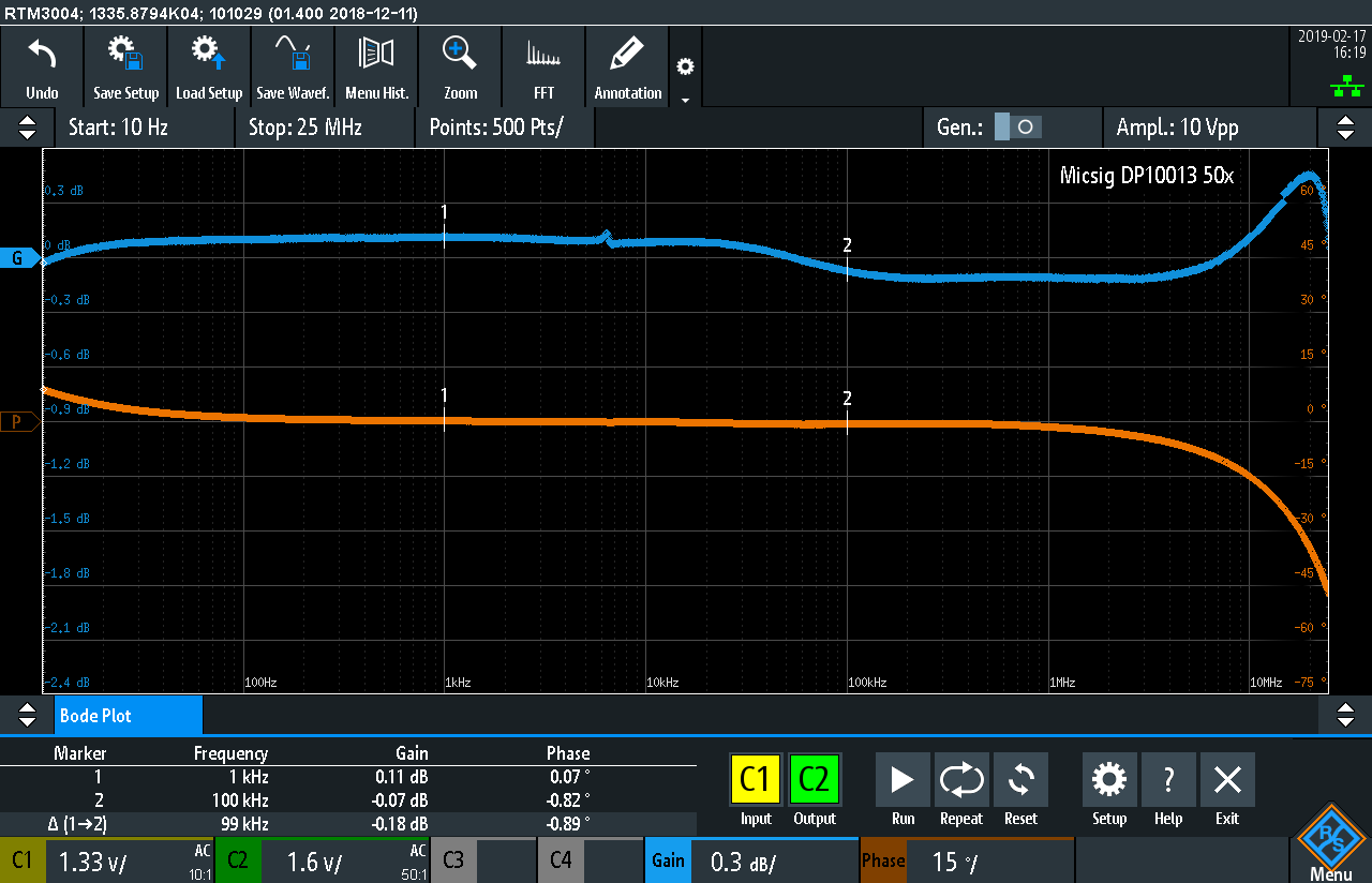
The Micsig was much more interesting, while attempting to be flat, there is actually quite a bit of deviation upwards at higher frequencies as if it’s an attempt to boost the upper frequencies.
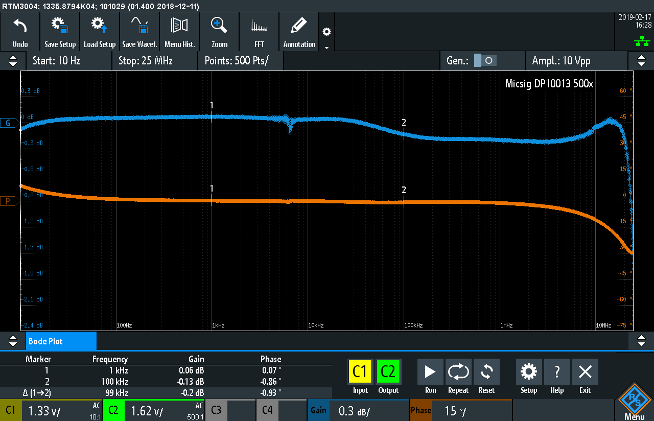
At 500x, the bump is less pronounced, although the response deviation seems a little greater. I’m not sure why but the horizontal grid-lines disappeared from this screenshot.
The thing I love most is that the K36 makes this type of testing as simple as connecting the probes to the right places and pushing a button. Nothing difficult, nothing complicated and potentially highly suitable for teaching analog electronics where testing passive/op-amp based filters would be a common laboratory experiment.
Experiment: TL974 Op-Amp Testing
Speaking of which, I decided to give a quick test of a Texas Instruments TL974INTL974IN opamp configured as a voltage follower to attempt to measure the gain-bandwidth product directly.

As the opamp is a rail-to-rail type, I powered it from a single ended 0-5V supply. To properly drive this, a virtual ‘ground’ needs to be established, but instead of doing so, the easier way to be to input a signal with an offset of 2.5V to centre it within the supply range. While not obvious, you can call up the “Gen” menu and set the offset which will be retained during the bode plot test – this allows you to have an AC signal on a DC bias as the test source.
In the case of the above, the voltage follower drops off before even 1MHz. Why? Well, it’s slew rate limited by the 3.3V p-p signal it’s attempting to follow.
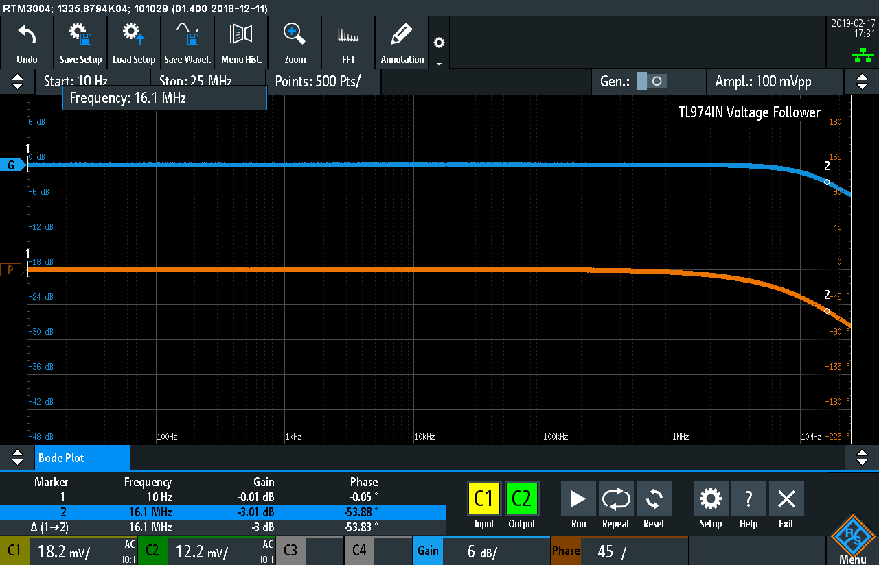
Dropping the signal to 0.1V p-p, the 3dB point is 16.1MHz which is quite respectable. The unit is expected to measure around 12MHz “typical”.
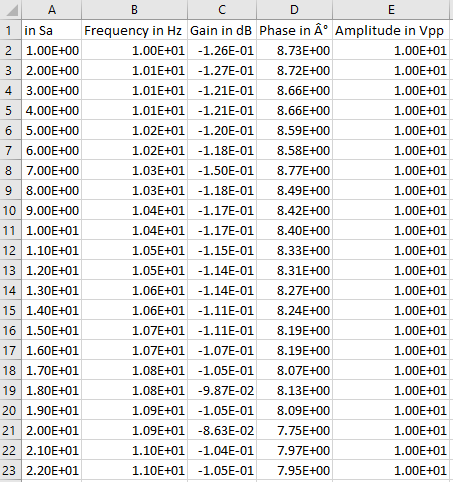
Data Export
The bode plot data can be saved into a .csv file for further analysis.

The exported format appears as below:
Conclusion
The new V1.400 firmware was “coming soon” for a while, but I’m glad it’s finally arrived. The big feature of this firmware is the K36 Bode Plot Analysis option which, when added to the instrument, allows it to automatically perform frequency response analysis through the range of 10Hz-25MHz with amplitude profile ability and up to 500-points per decade. In my testing, it proved to be quite intuitive to use and was faster than I initially expected.
The V1.400 firmware does fix the vast majority of functionality issues detected in my review with the V1.300 firmware, some of which resulted in lock-ups, which makes me rather happy even if the minor cosmetic issues remain unaddressed. Although I haven’t used this new firmware long enough to uncover any further issues, the improvements made definitely make the upgrade worthwhile.
It remains to be seen if or when the North American RTM3000/RTA4000-series oscilloscopes get the K18 Spectrum Analysis features, as it still appears to be unavailable at this stage.
EDIT: Fixed some formatting issues to make images a little more readable.
Top Comments