While my recently delivered Weller WXsmart RoadTest Review managed to achieve and exceed my proposal’s goals, I am not yet done with learning more about the system. Please note that this post contains a lot of my own thoughts and suppositions and cannot be treated as definitive. I cannot be held responsible for anything that may arise (not limited to damage or losses) from using, misusing or not being able to use any of the following information.
Table of Contents
A Little Interactivity
Now that I’ve had a chance to see my fellow RoadTester’s reviews (one from gpolder and one from john.porter ), perhaps it would be good to add a bit of interactivity to this bonus piece in the form of a poll. Oh, and before anyone asks, I’m not competitive at all *shakes head* not at all ... and let's hope this works because this is the first time I've tried making a poll in recent memory!
With that out of the way, back to the business at hand. No pun intended. I had mentioned in my review that I had a tip failure from overheating on initial start-up and an intermittent tip experience as well. Over the course of the review, the possibility that the WXMPS MS handpiece may have contributed became apparent, so having relayed this to Weller, they were happy to provide a replacement with the old one remaining in my possession.
I think it wouldn’t necessarily be great to just have the old unit hanging around – for one, it may cause problems down the track and for another, perhaps it wouldn’t be fair to Weller and the other RoadTesters that I have two handpieces.
So rather than leave it in a box, or to throw it out, I decided to sacrifice it in the name of science to help us learn a few things. What’s inside one of the handpieces? How does it talk to the “smart” tips? How does it talk to the base? How does the base perform thermal control?
Taking it Apart
Taking the unit apart is a somewhat destructive process. First, I slid the boot off the cable to reveal a crimp ring. This was pushed together to allow the cable to be freed.
From here, the front collar needs to be untwisted from the body. It is a very tight fit, so I needed the help of a vice and some pliers, resulting in damage to the body and the collar.
However, it did come apart, which is a good start. The collar is well connected to the body electrically, which is a good thing. The connector inside, while seemingly like a 3.5mm stereo plug, is a bit different in its physical construction.
Tugging on the connector inside allows the tightly packed circuitry inside to slide out. A piece of springy copper-coloured plate is used to provide a good grounding to the board as well.
It is otherwise insulated by polyimide tape with a production code/date code label. It seems to be a very tight fit, with the tape being cut somewhat while being extracted.
The board has six wires connected through the flexible cable to the base. These are red, black, purple, white, brown and blue. The board itself has a number of SMD components which we will look at a little more closely in a bit.
There are components on both sides, with programming test-pads on the rear. A very dense design.
Under the Microscope
It’s hard to get a good look without putting it under a microscope.
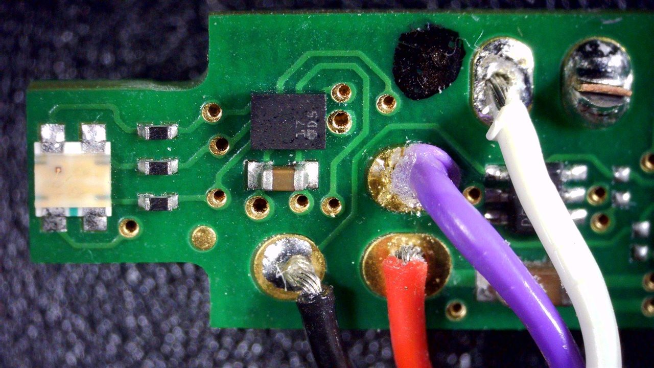
From the top left, we see an RGB LED, some series resistor and an SMD chip that is presumably an LED driver given where the connections are. Look at the small footprints – even the vias and solder-mask hole alignments are hard to maintain at this scale!
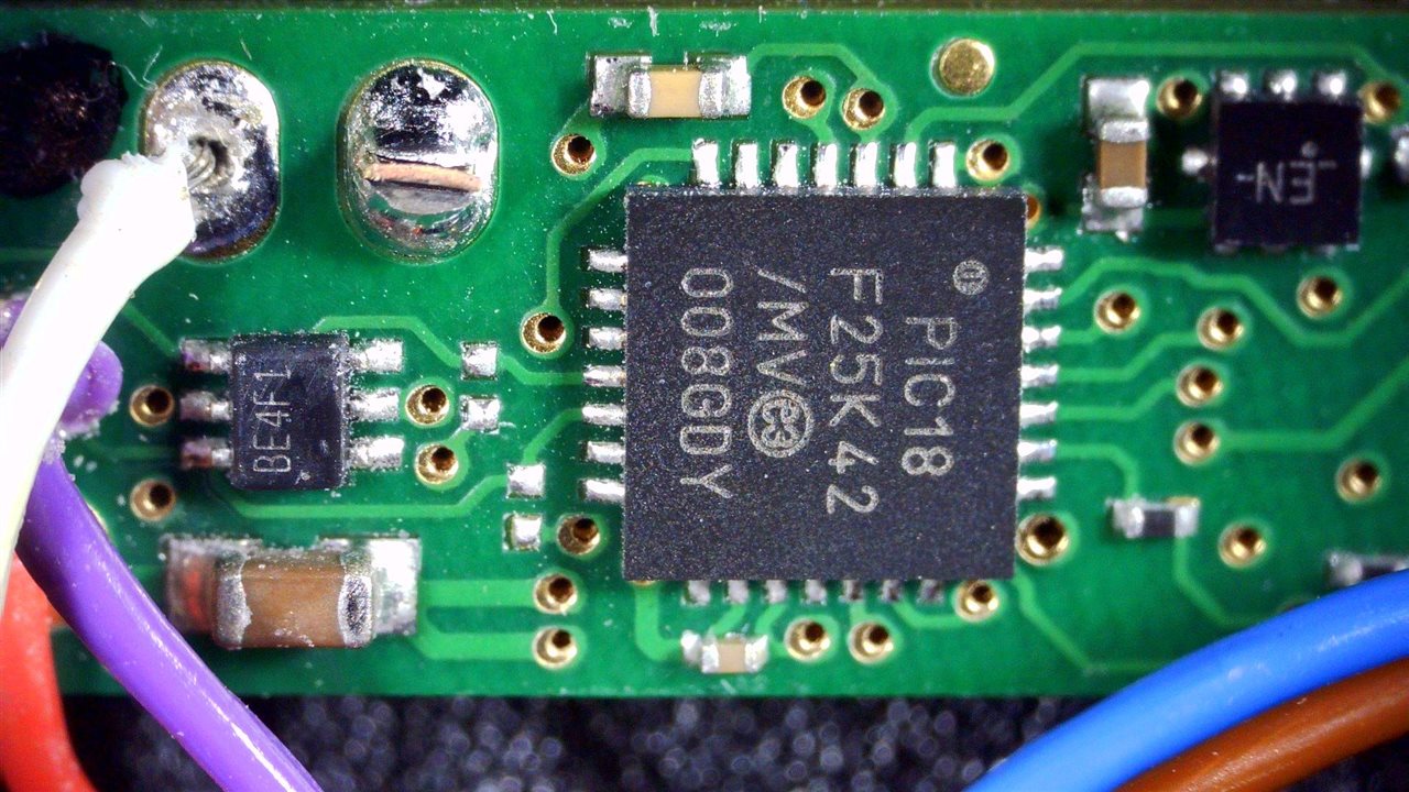
Shuffling along, there is an unidentified IC marked BE4F1 which I presume may be an isolator, line-driver of sorts. The main business is dealt with by the PIC18F25K42 microcontroller, with an IC marked EN next to it possibly being a voltage detector IC for brownout reset.
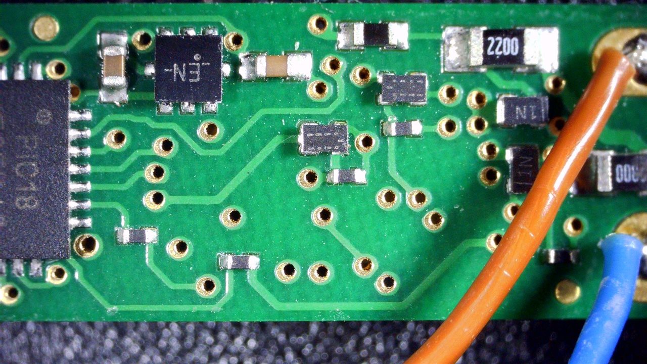
From there, there are a few resistors with two of them seemingly larger, perhaps for power sensing, some three-terminal SMD devices that may be FETs and some diodes.
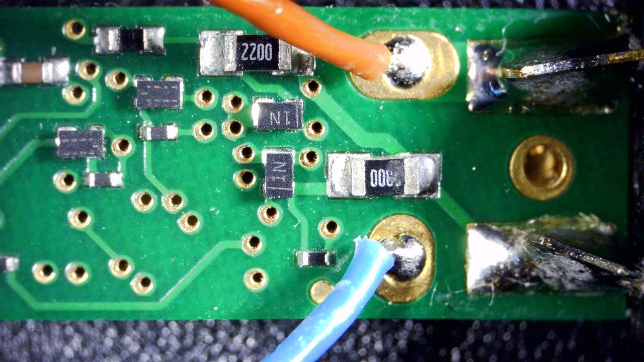
We then reach the area where the tip socket connects to the PCB.
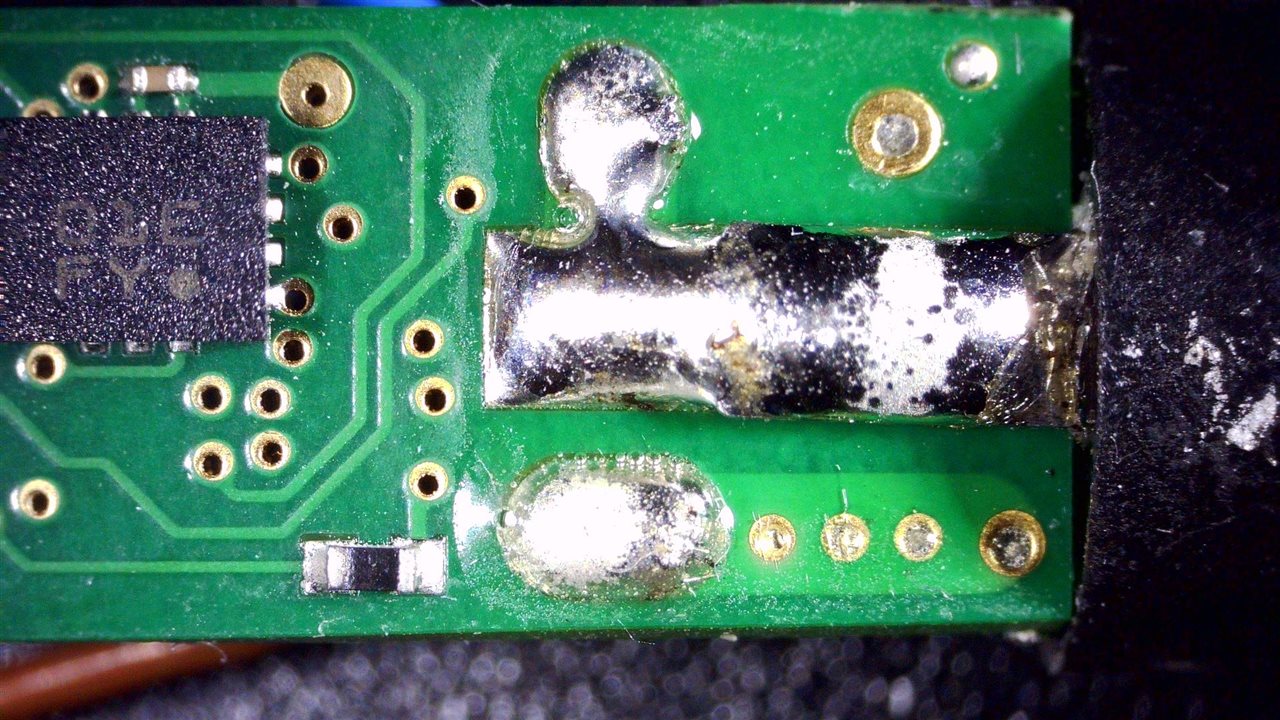
Flipping it over and going backwards, it’s clear that the brown and blue wires are directly connected to two poles of the three-contact plug, with the middle one going through some resistors and circuitry.
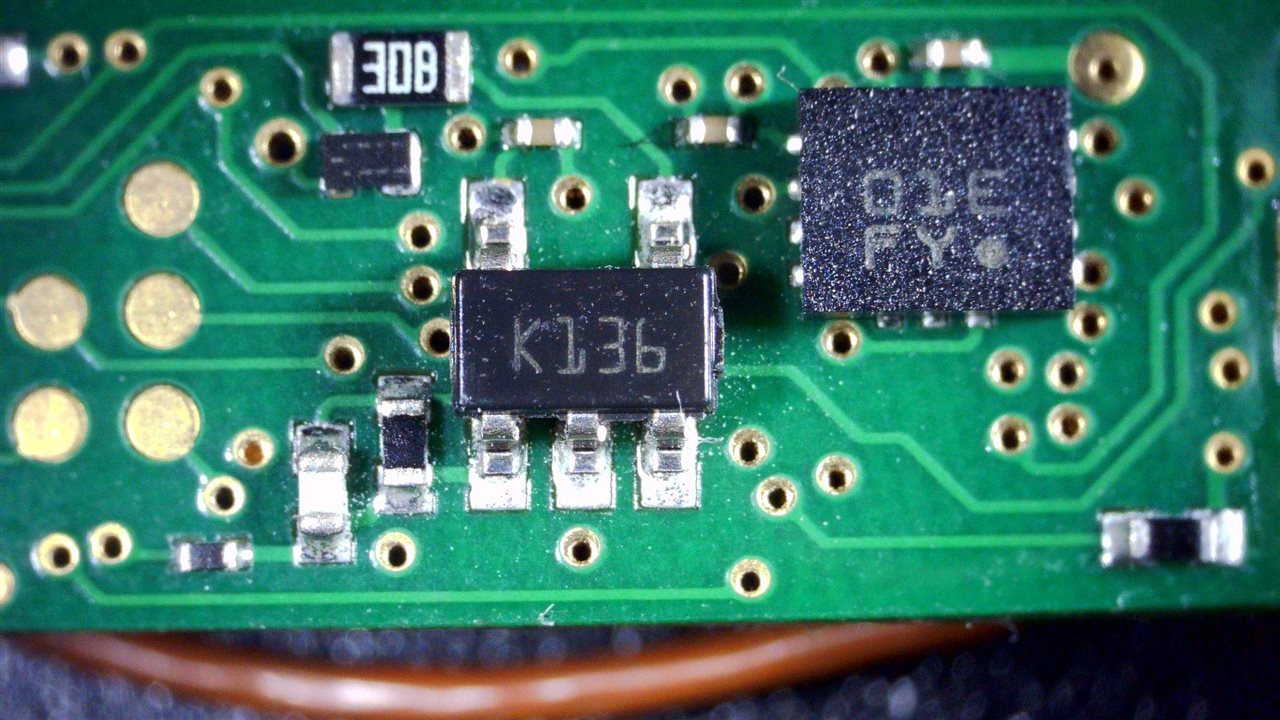
On the underside is a larger FET. Next to this is another IC marked 01E FY – I’m not sure, but at a guess, this could be the accelerometer for motion sensing. If not, then it could be an external memory (although I suspect the small memory requirements may mean that could be satisfied by the PIC alone), but I doubt it.
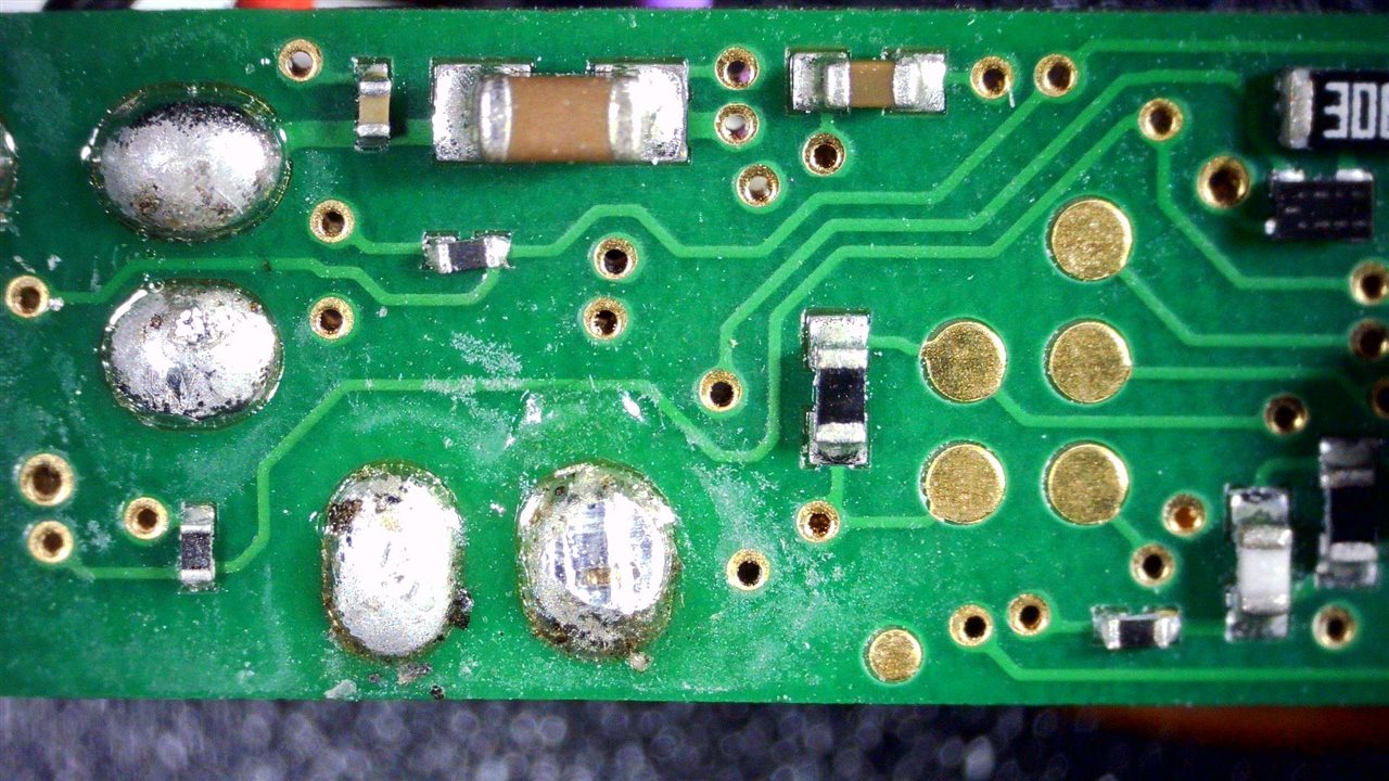
Programming pads are visible as well as the back of the soldered through-hole wire connections.
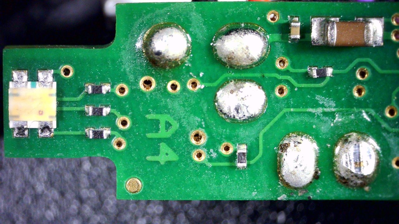
Finally, this side also has an RGB LED for balance … which is a nice touch, instead of relying on the light pipe to spread the light from one LED evenly all the way around.
What’s on Those Pins?
The next question is – with only three pins for the smart-tip and six connections to the handpiece from the WXsmart station, just how does it do all of the “magic” that it does when it comes to power control, temperature sensing, traceability records?
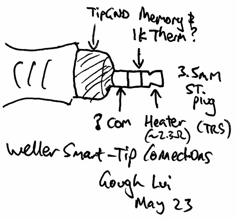
Measuring the tip pins with a multimeter gives a quick clue. It seems that, at a guess, the sleeve of the connector is a common pin and the tip is a heater contact as it has a very low resistance. The ring and sleeve resistance is about 1kΩ and does vary with temperature, making me suspect that it is a thermistor connection.
This still leaves the puzzle of how data gets to and from the tip. Does it hitch a ride on the power? Or does it hitch a ride on the thermistor connection? I would have to guess the latter.
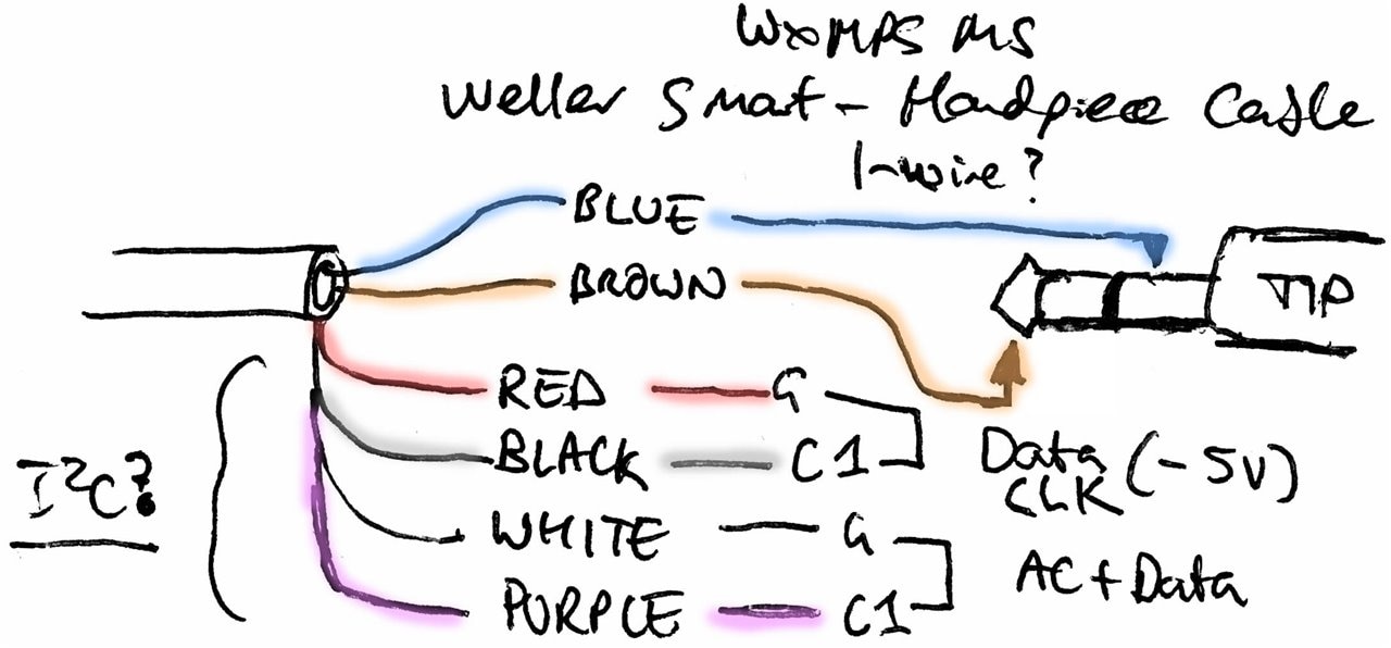
As for the handpiece connection, the blue and brown connections were already earlier traced directly to the tip connection. The remaining connections were a bit strange, however, as probing them with an oscilloscope did cause issues as we may have problems with ground. On the red/black pair, if I connect the oscilloscope ground to red and the channel to black, I get a series of what appears to be -5V data clock bursts at about 91kHz.


However, if I reverse the connection, the station drops the link entirely and stops registering the handpiece.
A similar behaviour appears for the purple and white connections – if I have ground connected to white and signal to purple, I can get some asymmetrical AC waveform with data riding on top.


Reverse the connection and the station drops the link as well. The asymmetrical AC does have me a bit concerned – perhaps I was measuring without a proper ground and inducted noise was getting in, but lifting the ground resulted in no sensible measurement. Likewise, it did dawn on me that the PIC and other circuitry needed a source of power as well, so perhaps the data is extracted from the AC power waveform by filtering.
This now brings to me the question of how does the tip itself get recognised by the station? I probed the 1kΩ thermistor connection referenced to the sleeve and saw that on initial plug-in of the handpiece with the tip connected, there was a flurry of data activity on this pin.


I don’t have any experience with this sort of signalling, but perhaps it’s some form of one-wire bus. After the flurry finishes, the line seems to return to about 0.5V which I presume means it is working as a regular thermistor only, but there is a “blip” every so often.

Perhaps this can be likened to an Ethernet “fast link pulse” to say that the tip is still alive, or perhaps it’s a poll in order to allow for starting a data transaction if necessary.

When no tip is attached, at first, it seems that it tries to provoke a data communication, then the line voltage flies upward as it probably attempts to operate the thermistor but instead of seeing a 1kΩ impedance, it’s seeing an open-circuit instead.
How Does the Heat Get Regulated?
One of the main reasons I pursued all of this is because of a comment on my unboxing video that wonders why the main base unit has a toroidal transformer in it in the first place. After all, its power rating is quite modest and switch-modes can be highly-efficient, quite capable at regulation and be a lot lighter, cheaper and universal-voltage as well. I did postulate that switchers may create stray voltages, RF noise, be vulnerable to poor power quality in ways that more linear-designs would not be. I also postulated that perhaps the AC is part of how the iron regulation works, being inherited from older Weller designs perhaps.
After the teardown I did and seeing the gang of Schottky rectifiers inside the case, I’m not so sure, so let’s seek an opinion straight from the tip!

As it turns out, the power supplied to the tip is full-wave rectified AC, complete with ripple. Therefore, the “12V AC” rating Weller gives to the handpiece and tips is perhaps more accurately DC with ripple … but that’s perhaps just a technicality.

When at full power for the conical tip I installed, it seems that the system operates on a 90ms time-base at 50Hz, letting through six cycles of nine cycles in that time period (66.7% duty cycle). Perhaps this actually makes sense, as for a 40W rating, I expected the tip resistance to be 3.6Ω but it measured 2.3Ω instead which would be 62W at 12V. Factoring in the duty cycle puts this back down to 41.76W which matches well with the rating! It’s great when the math lines up.

As the heating slows down, we can see that the system is able to let through two half-cycles or four half-cycles. It is very nice that it is zero-cross switched for minimum noise and stress. I’m not sure if it is capable of half-cycle switching (i.e. 1/9 duty).
Conclusion
Unlike previous blogs, this post involved a sacrifice in the name of science. But to be fair, this WXMPS MS was potentially problematic and had been replaced, so I felt it was only fair to learn from it instead of throwing it away or leaving it to sit in a box. In return, I’ve had the chance to learn and show exactly what is inside the handpiece and make some deductions about how communications and power are handled in the system. It’s definitely nice to see certain features like the zero-cross switching happening in practice and the fact that the math seems to line-up on duty-cycle and rated power. I hope you enjoyed this “spur-of-the-moment” bonus blog and I hope you voted as well.
Any questions, feel free to leave me a comment!

